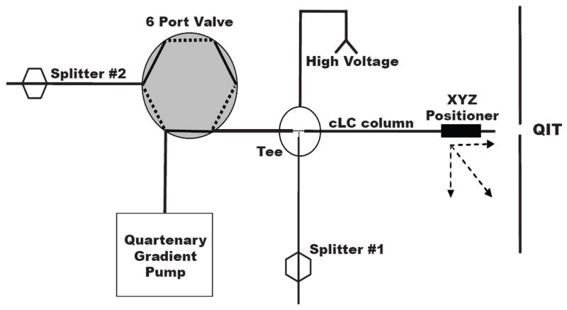
Figure 1.
Block diagram of capillary LC system illustrating splitters and voltage application. For sample loading, the 6 port valve is set in “load” position (flow path represented by dashed line), the column is removed from the tee, sample loaded onto column using gas pressure sample reservoir (500 psi) and then reconnected to tee. The valve is actuated to inject position (solid lines) and gradient initiated. With this configuration, the pump is maintained at near constant pressure during the entire experiment.

