
Figure 4.
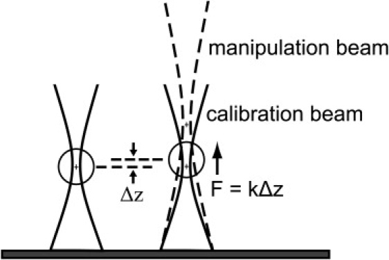
Mapping the optical potential. The manipulation beam (dashed lines) and the calibration beam (solid lines) are aligned laterally but have a different axial focus. First, a microsphere is trapped in the calibration trap of known stiffness k. When the manipulation beam is turned on, it exerts a small incremental force on the microsphere, which results in a displacement Δz. This displacement is measured for varying offsets between the axial foci of the two beams to map the potential of the manipulation beam as a function of axial position.