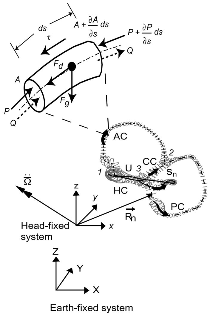
Fig. 1.
Membranous labyrinth geometry. The centerlines of the membranous labyrinth geometry of the right ear used in the present model are illustrated with respect to the head-fixed (xyz) and earth-fixed (XYZ) co-ordinate systems. HC – horizontal (lateral) canal, PC –posterior canal, AC – anterior canal, CC – common crus, utricular section. The trajectories of R⃗n define the centerline coordinates sn and the vector is the angular acceleration of the head, both resolved in the head-fixed coordinate system. An expanded view of a short section of the canal (length ds) with a free-floating particle is shown. P represents pressure along the centerlines of the canal, τ is the shear stresses at the wall, Q is the endolymph volume displacement and A is the local cross-sectional area of the canal. Fg is the force due to gravito-inertial acceleration and Fd is the interaction drag force between the particle and the endolymph.

