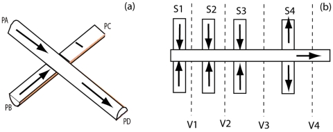
Figure 1.
(Left side) A simple crossing junction used as a design element in software and imaging calibrations; two inlet flows from PA and PB, single outlet flow from PD. No flow allowed through PC (wall boundary condition). The analysis channel is on top. The sheath channel is on bottom. Percentages of flow from PA and PB are in reference to PD, the total flow after the junction. (Right side) The four-level compensated vertical focusing device modeled in the text is illustrated. Additive sheath (symmetric sheath inputs S1 and S3) and additive analysis (symmetric S2) are combined upstream of a correction flow (symmetric S4). The device is driven by suction from a port at the right end. Adjustable flow resistances on the channels S1–S4 are used to tune the device. Planes chosen for cross-sectional viewing are on the order of ten channel dimensions downstream of the junctions and are indicated schematically as V1–V4.

