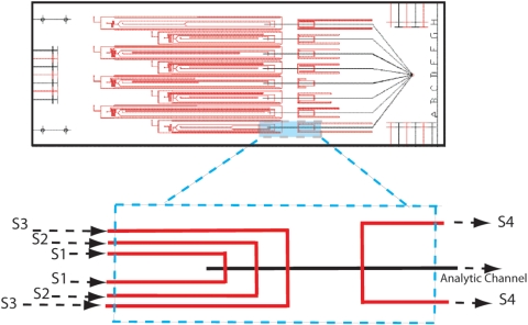
Figure 2.
Plan view layout of the device designed to test vertical focusing and subtractive compensation. Eight variations of the 4-sheath configuration shown in Fig. 1b, labeled A–H (right side of die), are included on the single test die. The two layers of etched channels are indicated as red (top plate) and black (bottom plate), respectively. A single laser-drilled hole is provided for each input or output [S1–S4, Fig. 1b] and for a common suction port (common to configurations A–H, right side of die). The full die size is 3×7 cm. Target flow ratios, controlled through calculated flow resistance for the eight variations, are given in Table 1 (see text).

