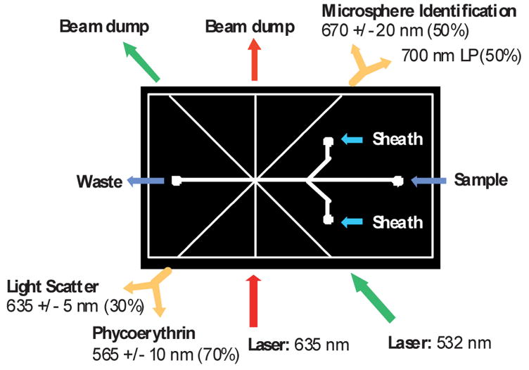
Fig. 2.

The PDMS module was 3.17 × 5.71 cm and had connections for optical fibers and fluidics as shown in the figure. Excitation fibers (bottom) were connected to the 635 nm and 532 nm lasers. Two multimode beam dump fibers were inserted across the channel from the excitation fibers (upper left) to capture excess excitation light and reduce scatter. The microsphere identification fiber (upper right) and the phycoerythrin/light scatter fiber (lower left) were each connected to a multimode fiber splitter. Each leg of the splitters was connected to a PMT as shown in the diagram.
