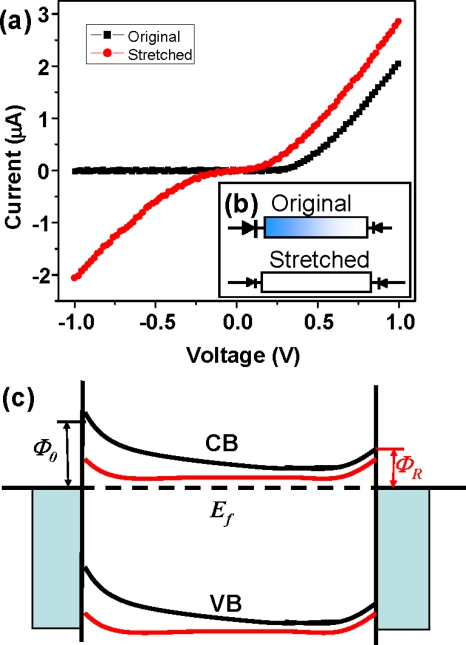
Figure 4.
(a) Changes of transport characteristics of a Ag/ZnO-nanowire/Ag device from linear I-V curve (black) to rectifying feature when stretching (red) the wire. (b) Circuit diagram models of devices for the corresponded I-V curves. The blue side is the negative piezoelectric potential side. (c) Schematic energy band diagrams illustrating the changes in band structure of the contacts at the two ends of the nanowire under tensile strain.

