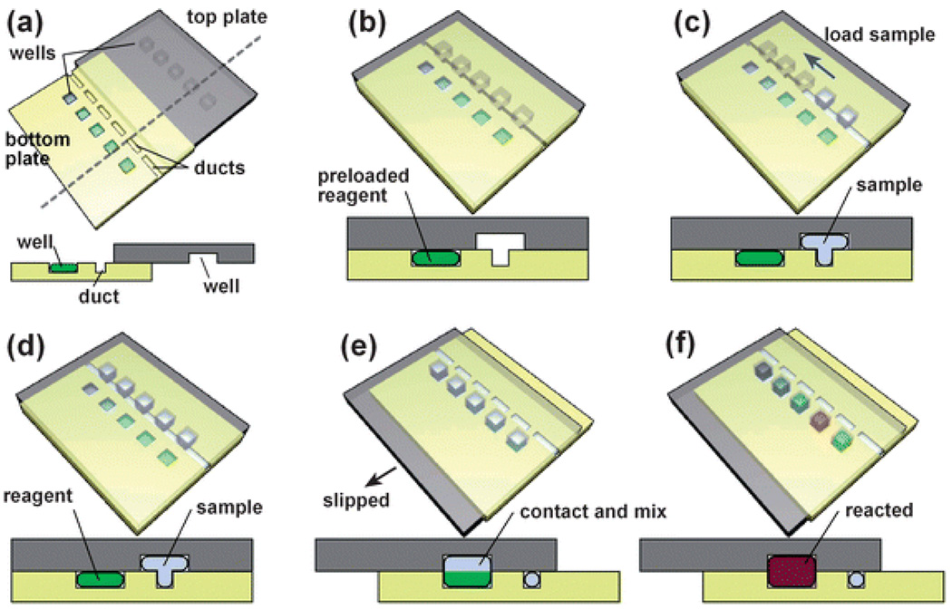
Fig. 1.
Step-by-step 3D schematic drawings with cross-sectional views that describe the operation of the SlipChip. (a) Off-set view that shows the preloaded wells of the bottom plate, the ducts of the bottom plate, and the wells of the top plate. (b) View of the device available to the user, in which the top and bottom plates are aligned. (c) and (d) Loading of a single sample through the overlapping ducts of the bottom plate and wells of the top plate. (e) Slipping of the top plate relative to the bottom plate disconnects the sample wells of the top plate from the ducts of the bottom plate, and then exposes the sample wells to the wells of the bottom plate containing reagents. (f) The red well schematically shows a reaction taking place after mixing and incubation (see also movie S1†).

