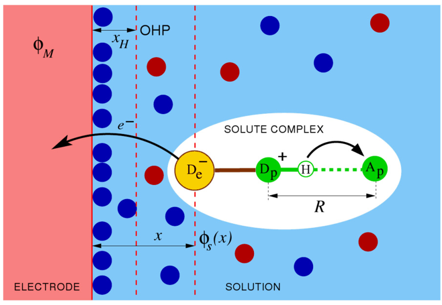
Figure 13.
Schematic picture of the electrochemical PCET reaction system comprised of a solute complex near the surface of a metal electrode in solution. The electron transfers from the electron donor De of the solute complex to the electrode, and the proton transfers from Dp to Ap within the solute complex. Filled circles represent the ions of the supporting electrolyte in the solvent, φM is the inner potential of the electrode, φ S(x) is the electrostatic potential in solution at a distance x from the electrode surface, x H is the distance to the outer Helmholtz plane (OHP), and R is the proton donor-acceptor distance within the solute complex. Figure reproduced with permission from Ref. 58.

