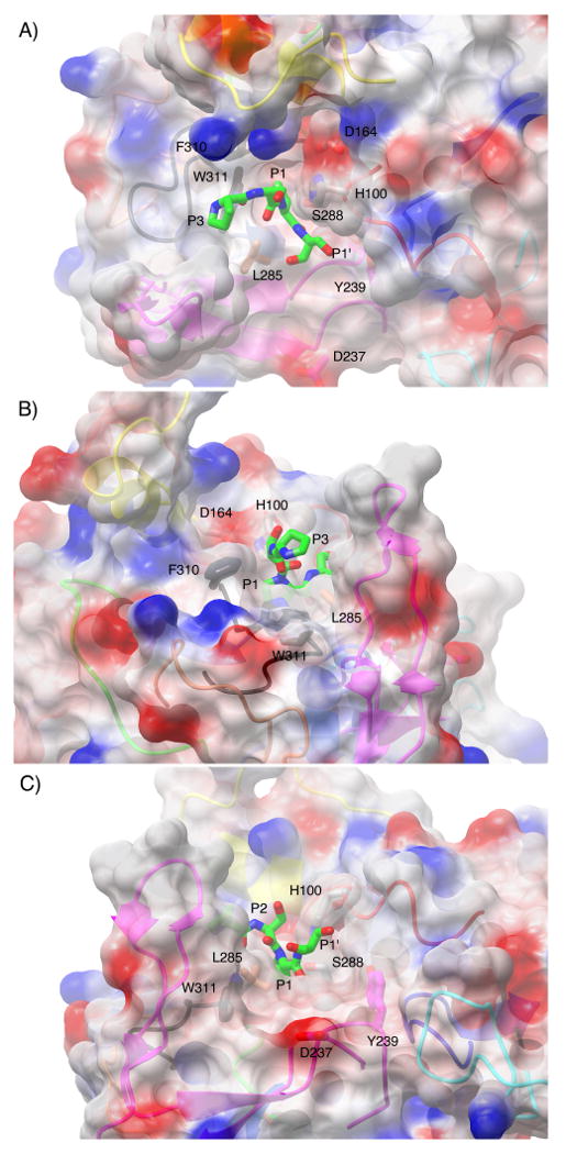
Figure 5.

Surface representation of the active site cleft of IgAP shown in a view from above (A), from the N-terminal direction of the hinge peptide (B) and from the C- terminal direction of the hinge peptide (C). The electrostatic surface is rendered semitransparent with the secondary structure of the protease domain that gives rise to the surface being rendered as a ribbon diagram and colored in an equivalent fashion to Figure 4. Those side chains that contribute to the formation of unique surface architecture of the active site are labeled and colored by atom type with the carbon atoms colored according to the loop region of which they are members. The catalytic triad is colored by atom type and rendered in grey. The P3-P1′ region (229P-S-P-S232) of the hinge peptide was manually modeled into the active site of IgAP based upon the position of the equivalent region in the elastase-turkey ovomucoid inhibitor complex.
