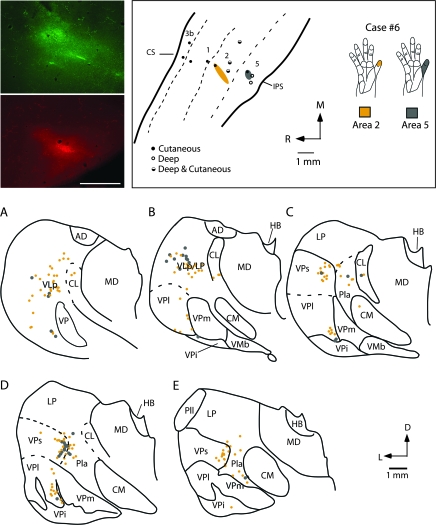
Figure 14.
Digital images of an injection of FE (green) placed in the representation of glabrous distal digit 1 of area 2 and an injection of FR (red) placed in the D1 representation of area 5 (top left panel). Electrophysiological recording sites for this case (case no. 6) are illustrated in the top middle panel and receptive field locations for neurons at each injection site are drawn in the top right panel. Labeled cell bodies resulting from those injections are drawn in coronal sections through the thalamus in (A–E). As in cases no. 3, 4, and 5 (Figs 8, 9, and 12), projections to area 2 were observed from VPs, VPl, and Pla. Labeled cells were also observed in VLp. The injection in area 5 was very small and resulted in labeled cells in VPs, Pla, and LP. Sections are 400 μm apart. Abbreviations in Table 1. Conventions as in previous figures.

