Abstract
Localized in vivo spectroscopy at high magnetic field strength (> 3 T) is susceptible to localization artifacts such as the chemical shift artifact and the spatial interference artifact for J-coupled spins. This latter artifact results in regions of anomalous phase for J-coupled spins. These artifacts are exacerbated at high magnetic field due to the increased frequency dispersion, coupled with the limited RF pulse bandwidths used for localization. Approaches to minimize these artifacts include increasing the bandwidth of the frequency selective excitation pulses, and the use of frequency selective saturation pulses to suppress the signals in the regions with anomalous phase. The goal of this article is to demonstrate the efficacy of optimal control methods to provide broader bandwidth frequency selective pulses for in vivo spectroscopy in the presence of limited RF power. It is demonstrated by examples that the use of optimal control methods enable the generation of i) improved bandwidth selective excitation pulses, ii) more efficient selective inversion pulses to be used for generation of spin echoes, and iii) improved frequency selective saturation pulses. While optimal control also allows for the generation of frequency selective spin echo pulses, it is argued that it is more efficient to use dual inversion pulses for broadband generation of spin echoes. Finally, the optimal control routines and example RF pulses are made available for downloading.
Keywords: pulse, optimal control, spectroscopy, optimized, bandwidth, localization
INTRODUCTION
1. The need for high bandwidth RF pulses for localized spectroscopy at high field
The advantages of in vivo spectroscopy at high field (> 3 T) include increased signal-to-noise (S/N) and increased spectral dispersion. However, the increased spectral dispersion also exacerbates localization artifacts that can significantly reduce the S/N of J-coupled spins and complicate analysis of the spectral content. All commonly used single voxel localization sequences such as PRESS (point-resolved spectroscopy), STEAM (stimulated-echo acquisition mode), and LASER (localization by adiabatic selective refocusing) are affected to varying degrees by the limited bandwidth of the frequency selective RF pulses used for the localization [1–3]. In addition to the chemical shift artifact in which chemically-shifted resonances are localized in spatially-shifted voxels, J-coupled resonances are subject to the spatial interference artifact [1]. This artifact arises because the J-coupled resonance signals occur with anomalous phase in regions where the spatially shifted voxels of the coupled spins do not overlap, and typically manifests itself as destructive interference resulting in an overall signal loss. As the relative shift of the voxel for chemically shifted resonances is proportional to the chemical shift differences (in Hz) divided by the pulse bandwidth in Hz [1], both of those artifacts are ameliorated by frequency selective RF pulses with increased bandwidths.
The bandwidth of a selective pulse of fixed length used for localization is invariably limited by the available RF power (or voltage). Stated in other terms, the bandwidth is limited by the maximum available B1 field (B1max). Although STEAM uses 90 degree pulses that have relatively large bandwidths, the STEAM signal is only half that of PRESS and LASER. The disadvantage of PRESS is the relatively low bandwidth of the spin echo pulses that are used. LASER [4] avoids both selective 90 degree and spin echo pulses, and instead uses selective inversion pulses in pairs for the localization, where each pair produces a properly phased spin echo. The advantage of LASER is that the inversion pulses can be made with larger bandwidths than even conventional 90 degree pulses. The disadvantage of LASER is the longer minimum TE that is required compared to PRESS and STEAM.
One proposed remedy for the narrow bandwidth pulses used in the PRESS sequence is to select a larger compartment than desired, and use frequency selective saturation pulses to reduce the voxel size and avoid the unwanted compartments with anomalous phase [5,6]. Large bandwidth saturation pulses are needed for this remedy to be effective. While the LASER sequence circumvents the problem of narrow band spin echo pulses with the use of dual inversion pulses, even with the higher bandwidth inversion pulses separate compartments for coupled metabolites can still exist at high field [3]. Still larger bandwidth (but short) dual inversion pulses that could function as spin echo pulses would be beneficial. Thus, improved (and short) selective excitation, spin echo, inversion, and saturation pulses would represent useful additions for high field in vivo spectroscopy.
2. RF pulse optimization
In early MRI development, optimal control methods provided one of the most effective means for design of frequency selective RF pulses [7,8]. Although optimal control methods have continued to be used for some RF pulse applications [9,10], the much more efficient Shinnar Le-Roux (SLR) methods became the RF pulse design method of choice [11] for MRI and in vivo spectroscopy applications that required frequency selective RF pulses. However, a large number of additional methods have also been shown to be useful, including numerical methods, particularly in the design of inversion pulses [12], which have also seen use in volume localization experiments [4].
Despite the effectiveness of the SLR design, there are a number of RF frequency selective pulse design criteria that are not amenable to the SLR method. In general, the SLR method does not provide for extension of the pulse bandwidth without increase of B1max. The primary exception is SLR-designed spin echo pulses, in which case the maximum voltage can be reduced by root reflection [13,14], with the reduced peak voltage enabling the pulse to be re-scaled for higher bandwidth [14]. Finally, frequency selective inversion pulse designs for higher bandwidth inversion pulses are available [12]. One disadvantage of the use of dual inversion pulses for generation of spin echo signals is the lengthening of the overall TE due to the length of the inversion pulses and the need for dual echoes. Ultimately, the bandwidths of these pulses are also limited by the available B1max.
Recently there has been a resurgence in the use of optimal control methods for the design of RF pulses, promoted primarily by the research groups of Glaser and Skinner. The Glaser and Skinner groups (G&S) have collaborated to both promote the efficacy of optimal control methods and demonstrate improved, broadband excitation by optimal control (BEBOP) pulses and broadband inversion by optimal control (BIBOP) pulses [15–17]. Some of their other designs include excitation pulses to accommodate relaxation [18], and demonstration of universal rotations generated from point-to-point transformations [19]. Although G&S have also used optimal control to generate what they term “pattern pulses” [20] to generate an arbitrary spatial pattern in an MRI experiment, they do not appear to have published conventional frequency selective RF pulses for use in MRI or in vivo spectroscopy.
G&S recently demonstrated that excitation pulses could be made more efficient (shorter) by allowing a linear spread of phase with frequency [21]. If the phase spread is small, it can be corrected by conventional processing (first order phase correction). In addition, this type of pulse is useful in spin echo experiments, where the timings can be adjusted to re-coalesce the magnetizations at the time of the echo. Among their innovations, they demonstrated that limiting the peak power (or B1max) could be incorporated into the optimal control method, and that the cross product of the forward magnetization and vector Lagrange multiplier could be used to correct the B1 field (See below)
While G&S have recently demonstrated the best-performing (in terms of lower B1max and shorter pulse length) broadband excitation and inversion pulses for high resolution NMR, there have also been some very recent advances in broad bandwidth frequency-selective pulses. The best-performing (in terms of bandwidth, given limits in B1max and pulse length) frequency selective saturation pulses have been designed through an extension of the SLR method that produces a polynomial-phase response [22], designated here as S-P pulses. Finally, the best performing spin echo pulses have been designed first by the SLR method, followed by sophisticated root-reflection schemes to obtain the lowest B1max pulses, which are then reconfigured into the broadest possible bandwidth spin echo pulses [14], designated here as S-K pulses.
The goal of this article is to demonstrate that optimal control methods as described by G&S can be extended to either improve the bandwidth and selectivity of conventionally designed frequency selective pulses under conditions of limited available B1max and fixed length, or reduce the length of the pulse while maintaining the bandwidth and selectivity. The optimal control methods are used to demonstrate examples of frequency selective excitation, inversion, and saturation pulses with improved bandwidth compared to previously published pulses of comparable B1max and pulse length. These new pulses are designed for improvement of single voxel in vivo spectroscopy experiments and offer excellent frequency selectivity. To verify the validity of the optimal control algorithms, a suite of optimized pulses (broadband excitation and inversion pulses, and frequency selective saturation and spin echo pulses) was generated and compared to the best examples of these types of pulses in the literature [12,14,16,22].
METHODS
The 4.0 T Bruker MedSpec instrument at the Center for Imaging of Neurodegenerative Diseases (CIND) is used with a 7 kW RF amplifier, which provided a maximum B1 field of 30 micro–Tesla (µT) in a transmit/receive head coil loaded with a normal human head. Thus, the B1 field was limited to 30 µT (1.28 kHz). Recent simulation studies indicated that, for a bandwidth of 8 kHz, the compartments generated by the localization pulses at 4.0 T would be quite small and could be ignored for virtually all brain metabolites, with the possible exception of lactate [3]. Thus, present efforts were aimed at design of 8 kHz bandwidth pulses without exceeding 30 µT in B1 strength. Although measurements of the B1 inhomogeneity over the human head at 4.0 T showed that the inhomogeneity with various headcoils approached (and with some coils exceeded) +/−20%, most single voxel experiments are conducted over a relatively small volume, and a goal of pulses that would perform well over a B1 inhomogeneity range of +/− 5% was adopted.
The optimal control method is well described by reference 15, and references therein. The optimal control method starts with an initial RF sequence. Very briefly, as applied to RF pulse optimization, optimal control attempts to make the forward path (in which the RF sequence takes the initial magnetization towards the desired state) as close as possible to the reverse path (in which the desired state is taken by the reverse of the RF sequence towards the initial magnetization). The vector Lagrange multiplier at the final time point is identified as the desired final magnetization to be run in the reverse direction towards the initial magnetization. At each time point, the difference between the forward and reverse paths provides the direction of change needed to be applied to the RF sequence to bring the paths closer together (i.e., to be optimized). As discussed in reference 15, this provides a very efficient optimization algorithm.
To facilitate the design and examination of the new pulses, optimal control routines were incorporated into the MatPulse software package [23] with separate menus for broadband non-selective pulses, and for frequency selective pulses. Optimal control theory applied to RF pulse design has been described a number of times in the literature. [7–10, 15–17]. In general, the MatPulse algorithms followed that outlined in [15]. There are, however, some differences. In the nomenclature of reference 15, M(t) is the magnetization at time point t, where t is incremented from 0 to the pulse length tp by δt, ωe is the B1 field, and λ represents the vector Lagrange multiplier.
The outline of the MatPulse optimal control routines, following the nomenclature in ref 15, is:
Choose an initial RF sequence ωe(k).
Evolve M forward in time from the initial state
Evolve λ backwards in time, starting from the target state F
Correct ωe(k)(t) at all time points by ωe(k + 1)(t) =ωe(k)(t) + ε [M(t) x λ (t)]
If the difference between M(tp) and F is increased, reduce ε and repeat the calculation of M(tp)
For any ω > ωmax, set ω = ωmax
Repeat steps (ii) through (vi) until a desired convergence is reached.
For step (v), a tolerance can be set to allow a slight increase in the difference between M(tp) and F, as we found that the residual (absolute linear difference between the states M(tp) and F) was often increased slightly early in the optimization. In addition, the algorithm limited the number of times ε could be sequentially reduced before continuing to another iteration.
In addition, as the cross product M(t) x λ (t) depended equally on the time points t and t+δt, with the exception of the end points ω (0)and ω(tp), ω(t) was corrected by:
The MatPulse algorithms allowed three options for setting the value of ε. The user could set a fixed value for ε; the user could set the program to choose a near-optimal value for ε every hundred iterations; the user could allow the program to adjust ε every hundred iterations, where the program increased ε if the residual never increased, or decreased ε if the residual increased more than a few times in the previous hundred iterations. As the optimal value for ε appeared to change significantly over even a few iterations, the latter option, which could be viewed as averaging over a number of iterations, was used for the most part for the optimizations in this work. Additional details of the MatPulse implementation are given in the Appendix.
The display of pulses, pulse profiles, and contour plots were all generated with MatPulse [23]. For experimental demonstration of the spectroscopy excitation and saturation pulse profiles, the excitation or saturation pulse was used as the initial excitation pulse in a PRESS sequence, and the magnetization profile read out by applying a gradient in the appropriate direction following application of the rest of the localization sequence on a silicon oil phantom. For the spectroscopy inversion pulse, dual inversion pulses were inserted into a LASER sequence, so that the spin echo magnetization profile resulting from the dual inversion pulses was read out.
RESULTS AND DISCUSSION
1. Comparison of MatPulse Optimal Control-Designed Pulses with Pulses from the Literature
i) Comparison of BEBOP broadband excitation pulse and BIBOP broadband inversion pulse
Results
The literature pulses from the G&S groups were downloaded from the webpage at: http://www.org.chemie.tu-muenchen.de/people/bulu/
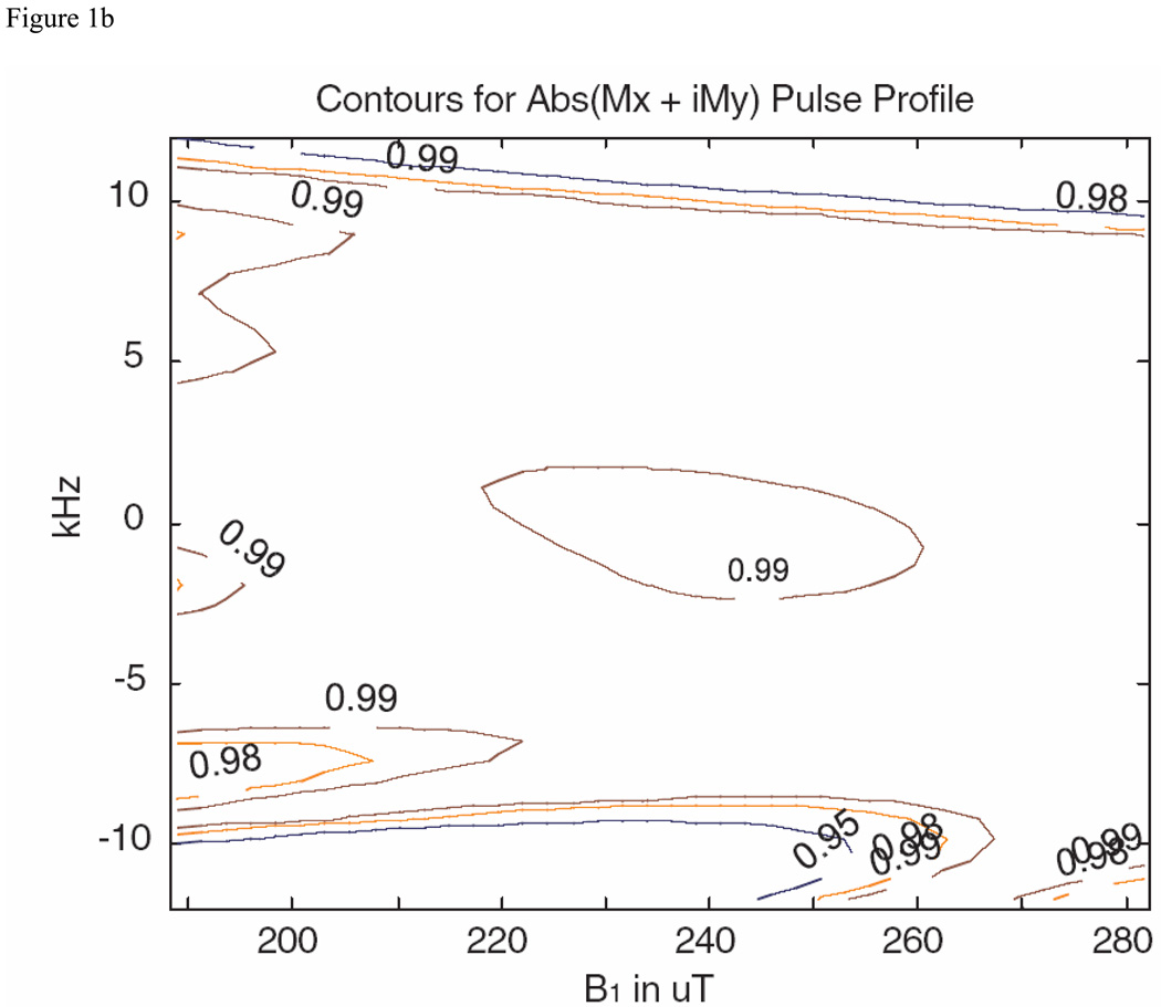
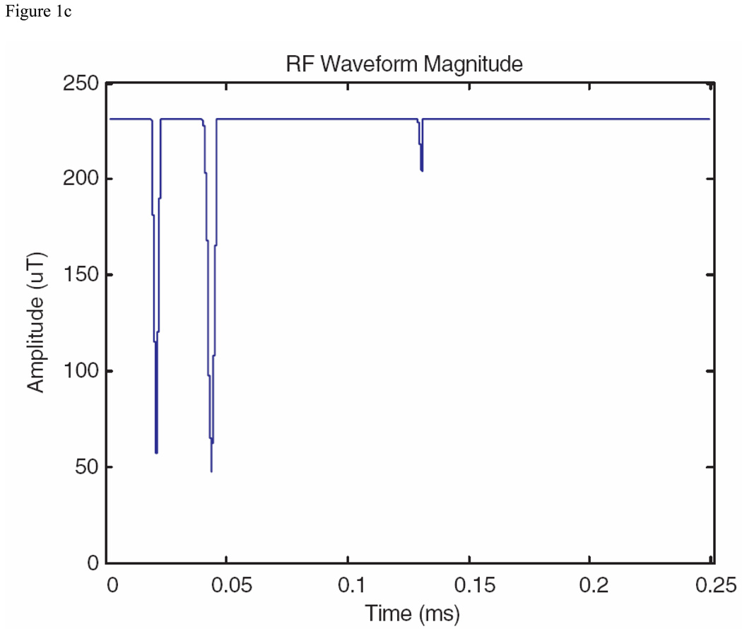
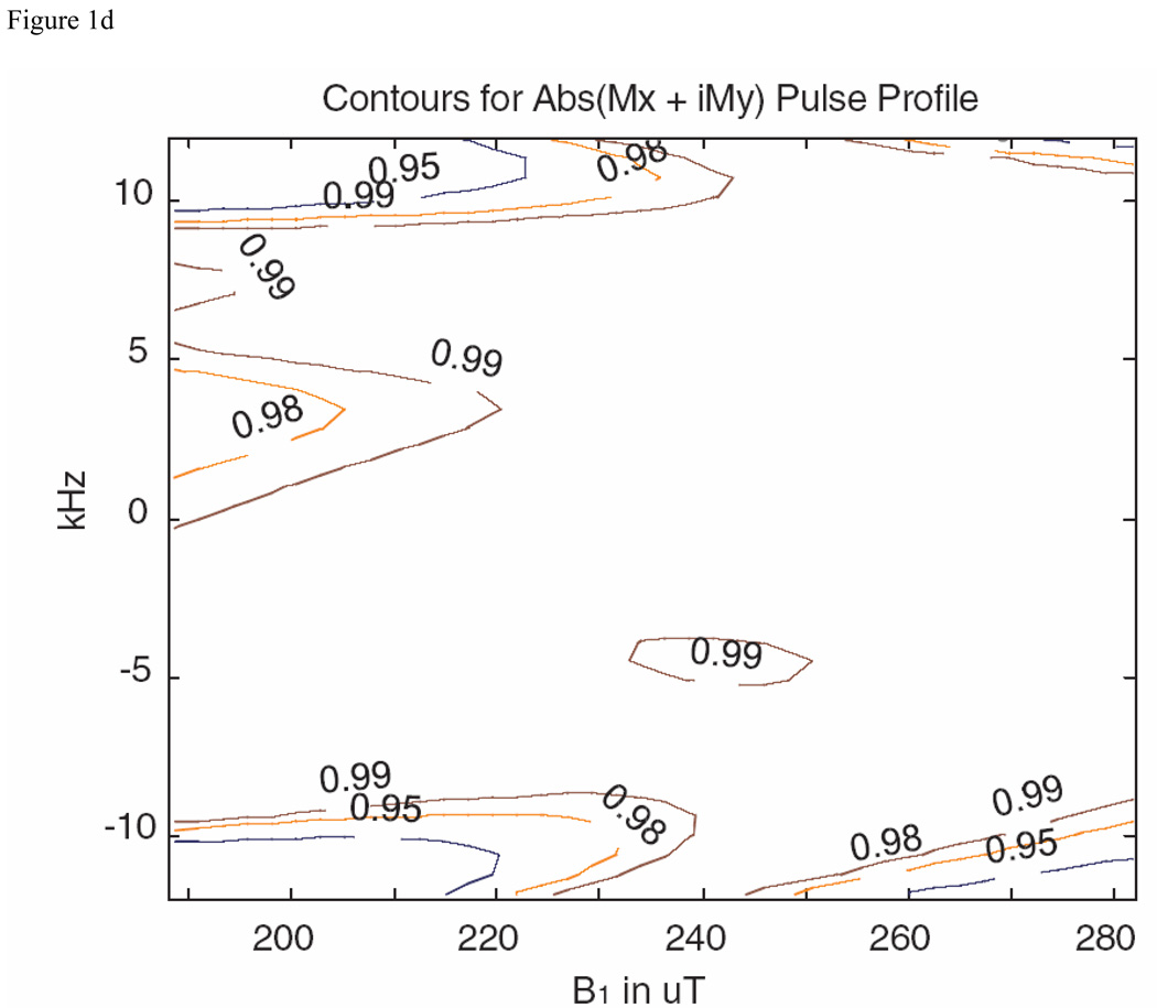
For the literature BEBOP amplitude-limited pulse we chose, under Excitation pulses, from category 2: Pulses optimized for a constant offset range of 20 kHz and different tolerances to RF-inhomogeneity. The nominal B1max for these pulses was 10 kHz, or 234 µT. The RF pulse with 495 points, 0.5 µs dwell time, and RF-inhomogeneity tolerance of +/−20%, was selected. The magnitude and performance as a function of frequency offset and B1 strength are shown as Figs. 1A and 1B. The contour lines for Fig. 1B are at 0.99, 0.98, and 0.95, the frequency range is over +/− 12 kHz, and the range over B1 is +/− 20%. For the comparison pulse, the optimization was initiated with a 495 point random pulse, with the results for the pulse magnitude and performance shown in Figs. 1C and 1D, where the parameters for Fig. 1D are the same as for Fig. 1B.
Fig. 1.
S&G BEBOP (excitation) pulse from reference 16, as described in the text, and comparison pulse obtained with the MatPulse optimal control routine. (A) Magnitude of the S&G excitation pulse in µT. (B) Bloch equations contour plot of the pulse performance as a function of frequency offset and B1 strength. (C) Magnitude of the comparison pulse magnitude in µT. (D) Bloch equations contour plot of the comparison pulse performance as a function of frequency offset and B1 strength.
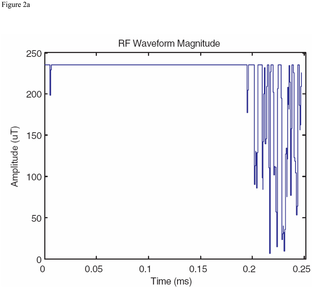
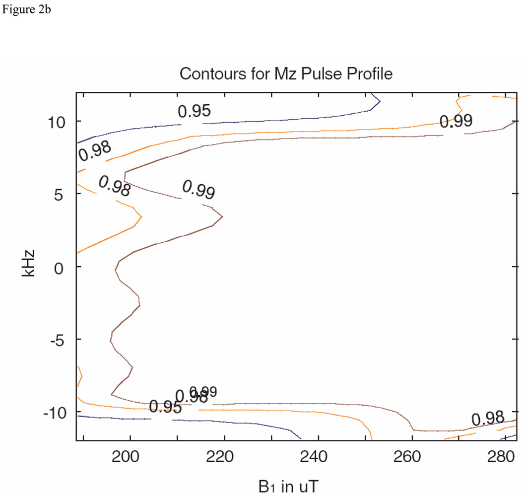
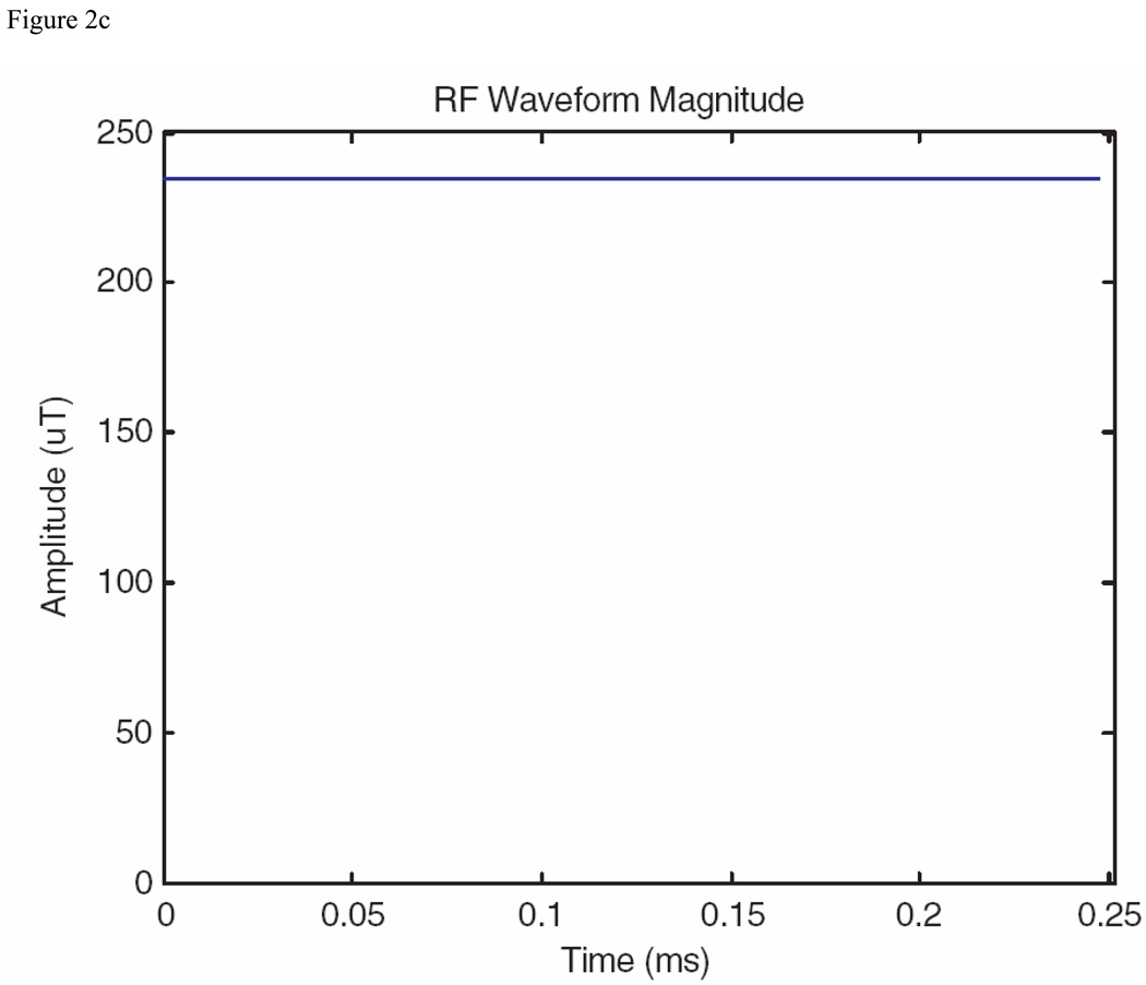
For the literature BIBOP amplitude-limited pulse we chose, from the above website, under Inversion pulses, from category 2: Pulses optimized for a constant offset range of 20 kHz and different tolerances to RF- inhomogeneity. The nominal B1max for these pulses was 10 kHz, or 234 µT. The RF pulse with 495 points, 0.5 µs dwell time, and RF-inhomogeneity tolerance of +/−20%, was selected. The magnitude and performance as a function of offset frequency and B1 strength are shown as Figs. 2A and 2B. The contour lines for Fig. 2B are 0.99, 0.98, and 0.95, the frequency range is over +/− 12 kHz, and the range over B1 is +/− 20%. For the comparison pulse, the optimization was initiated with an HSn pulse [4] with n = 2, with the results for pulse magnitude and performance shown in Figs. 2C and 2D. The parameters for Fig. 2D are the same as for Fig. 2B.
Fig. 2.
S&G BIBOP (inversion) pulse from reference 16, as described in the text, and comparison pulse obtained with the MatPulse optimal control routine. (A) Magnitude of the S&G inversion pulse in µT. (B) Bloch equations contour plot of the S&G pulse performance as a function of frequency offset and B1 strength. (C) Magnitude of the comparison inversion pulse magnitude in µT. (D) Bloch equations contour plot of the comparison pulse performance as a function of frequency offset and B1 strength.
Discussion
The optimal control routines implemented in MatPulse were patterned after those discussed in the G&S articles [15–17]. As proof of the soundness of the implementation, it is shown that the MatPulse routines are able to essentially reproduce selected BEBOP and BIBOP pulses demonstrated by the G&S groups.
Comparison of contour plots of Figs. 1B and 1D shows our BEBOP comparison pulse to be roughly comparable to the selected G&S BEBOP pulse, although the G&S pulse performance is slightly superior at the low B1 values. While the performance of our initial trial did not quite match that of the G&S BEBOP pulse, this was to be expected, as optimal control essentially finds a local rather than global optimization, and as shown by the extensive optimizations performed by the G&S groups [16], initiating the routine with random pulses produces a small range of performance of the resulting pulses. For the broadband pulses, the longer the optimization was continued, the more the amplitude tended towards the maximum allowed value, albeit typically with only slight improvement of pulse performance. As our optimizations were typically run overnight, the difference in amplitudes between our pulses and the G&S pulses was probably due to the longer optimization time used for generation of our pulses.
On the other hand, comparison of contour plots of Figs. 2B and 2D shows our BIBOP comparison pulse to have significantly improved performance over the selected G&S BIBOP pulse. The contour plots show our comparison pulse to be significantly better at both low and high B1 fields. We suggest that this may be due to initiating the optimization with a good initial pulse, rather than a random pulse. This result suggests that, when suitable initial pulses exist, it is advantageous to use them as initial pulses for submission to the optimal control routine. This is consistent with the local, rather than global, optimization characteristics of the optimal control method.
ii) Comparison of saturation and spin echo pulses
Results
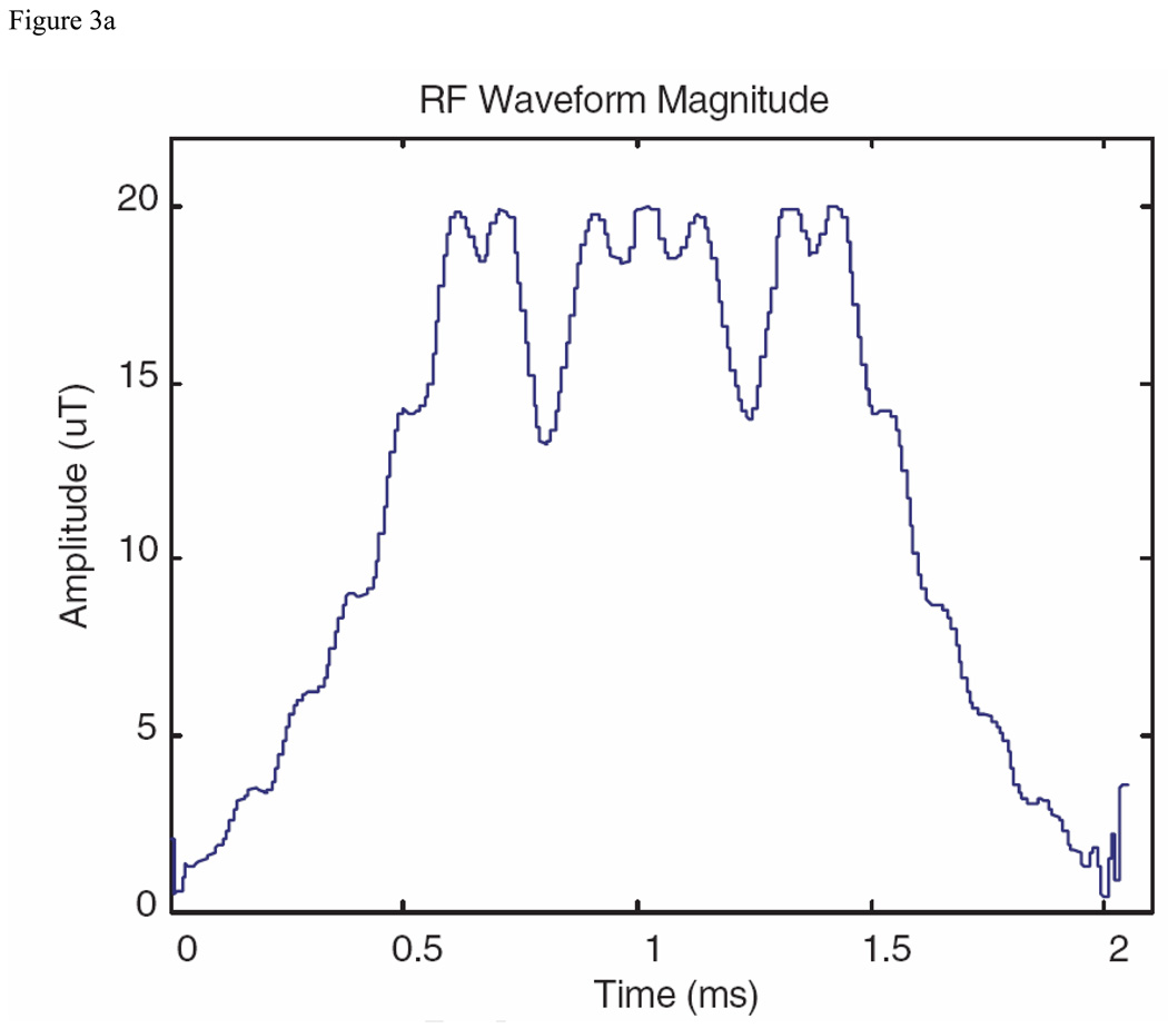
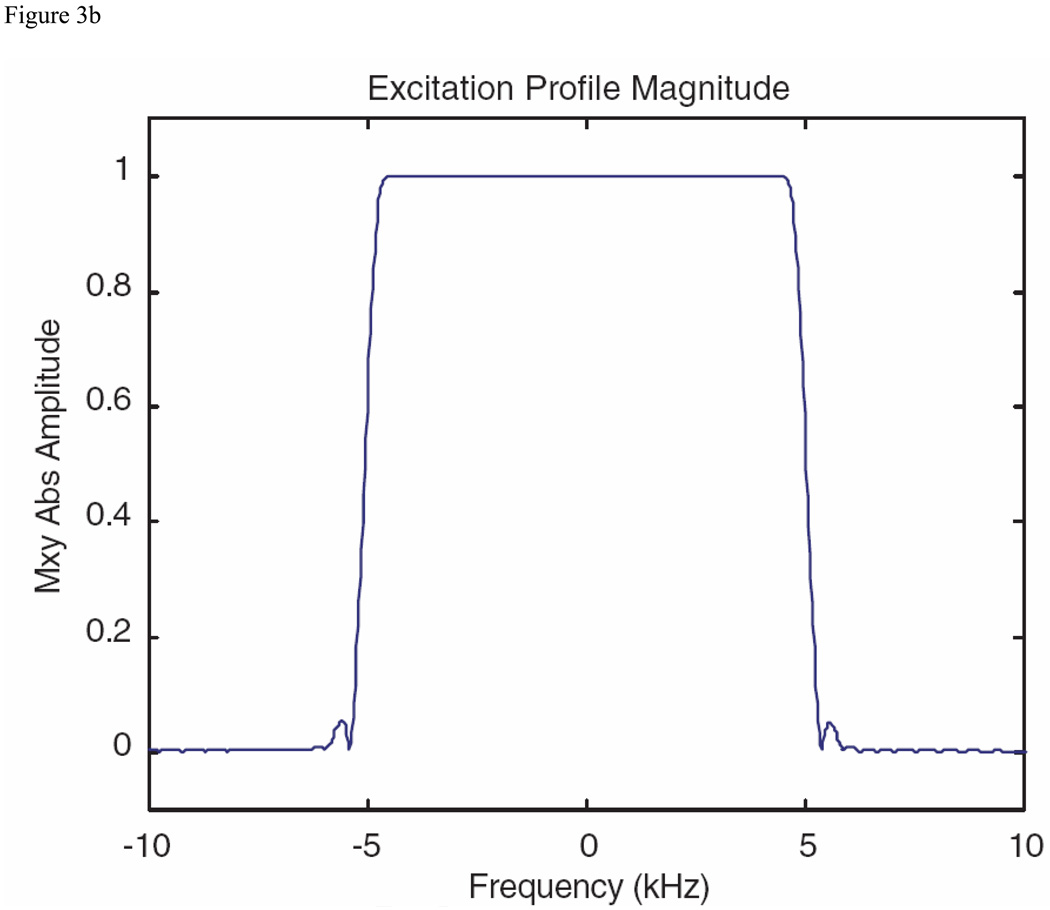
For the saturation pulse comparison, parameters were chosen to duplicate the 10 kHz polynomial-phase saturation pulse shown by Schulte et al. [22] in their Fig. 5, where the B1max was 20 µT. The magnitude of the pulse produced by the MatPulse optimal control routine (using a hyperbolic secant pulse as the initial pulse) is shown in Fig. 3A, while the excitation profile (magnitude of the transverse magnetization) is shown in Fig. 3B. These figures are to be compared to the S-P pulse magnitude and profile demonstrated by reference 22, Fig. 5.
Fig. 3.
Comparison saturation pulse produced with the MatPulse optimal control routine, to be compared with Fig. 5 of reference 22. (A) Magnitude of saturation pulse in µT. (B) Magnitude of Bloch equations pulse profile (transverse magnetization) with the saturation pulse performing as an excitation pulse.
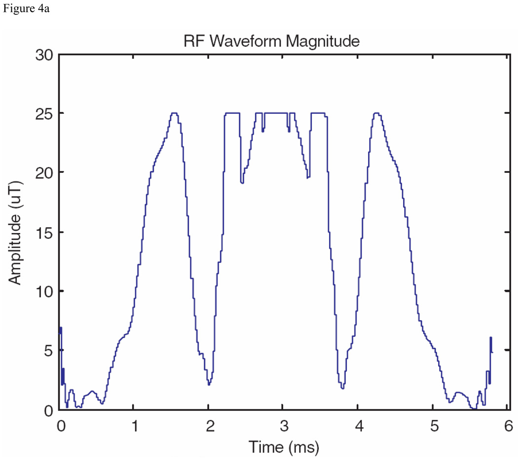
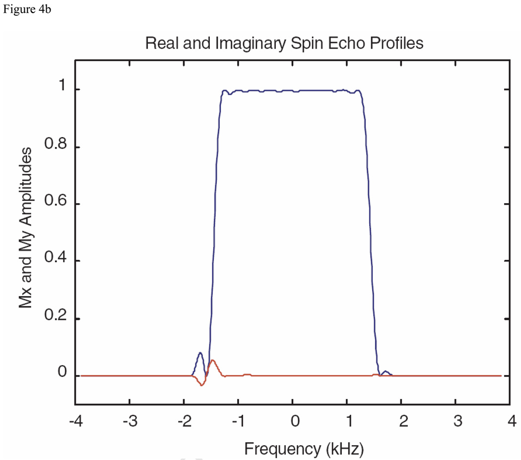
Using sophisticated root reflection schemes, Schulte et al. [14] have displayed in their Fig. 4 and Fig. 5 what they term a suite of exemplary broad bandwidth spin echo pulses designated here as S-K pulses. These pulses were designed for a tip angle of 172 degrees with a B1max of 24 µT, and the authors showed a roughly linear increase of pulse length with bandwidth. For their fourth pulse, they used a time of 5.8 ms to achieve a bandwidth of 3.0 kHz, with a transition bandwidth of 18% (18% of the bandwidth) [14]. For a comparison pulse, the MatPulse optimal control routine was initiated with a SLR spin echo pulse, where the optimization was for 180 degrees and a B1max of 25 µT. The magnitude of the resulting pulse is shown in Fig. 4A, and real and imaginary (Mx and My) crushed spin echo profiles of the pulse are shown in Fig. 4B.
Fig. 4.
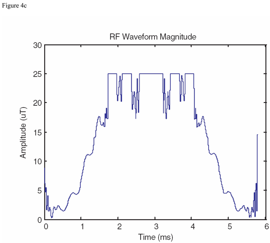
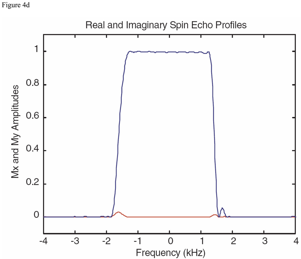
Comparison spin echo pulses produced with the MatPulse optimal control routine, to be compared with Fig. 4 and Fig. 5 of reference 14. (A) Magnitude of a comparison pulse initiated with a SLR root reflected spin echo pulse. (B) Real and imaginary (Mx and My) Bloch equations crushed spin echo profiles of the comparison pulse of A. (C) Magnitude of a comparison pulse, initiated with a cascaded 90 degree pulse as described in reference (S&G) and discussed in the text. (D) Real and imaginary (Mx and My) Bloch equations crushed spin echo profiles of the comparison pulse of C.
Fig. 5.
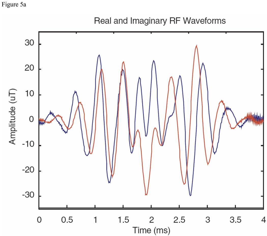
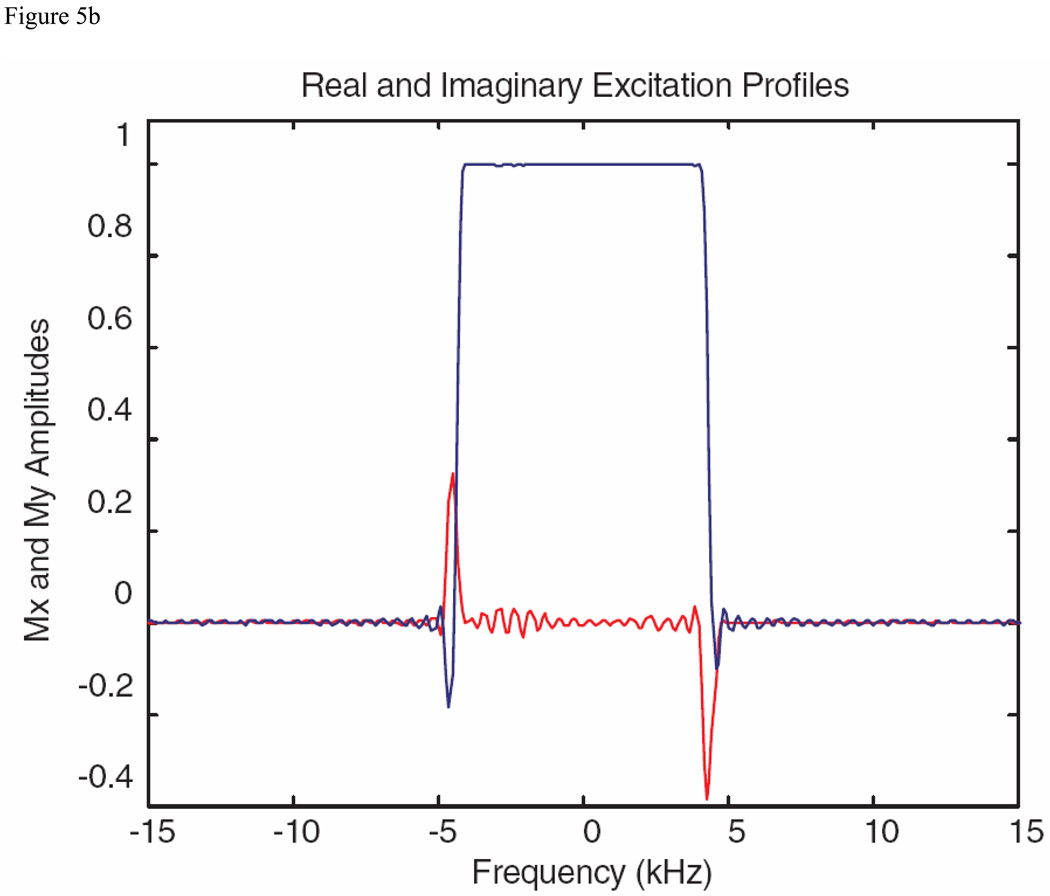
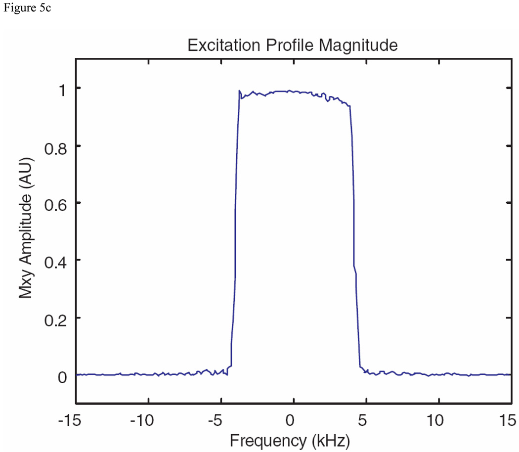
Excitation pulse example with a bandwidth (at the top of the profile) of 8 kHz produced with the MatPulse optimal control routine, with a B1max of 30 µT. The pulse was initiated with a 10 kHz SLR pulse with a B1max of over 60 µTesla. (A) Real and imaginary components of the optimized excitation pulse. (B) Real and imaginary components (Mx and My) of the Bloch equations pulse profile following gradient refocusing. (C) Experimental magnitude profile in arbitrary units (AU) produced by the excitation pulse. Additional details of the experimental profile are discussed in the text.
Another method for spin echo pulse design has been presented by Luy et al. [19], in which a 90 degree excitation pulse is concatenated with a time reversed and phase inverted version of itself. For this approach, the MatPulse optimal control routine was first used to optimize a 3.0 kHz, 2.9 ms 90 degree excitation pulse with coalesced magnetization, with a B1max of 25 µT. Although the performance of the initial pulse was not of very good quality, the concatenated version proved adequate to serve as an initial pulse for submission to the optimal control routine for a spin echo pulse. The magnitude of the resulting optimized pulse is displayed in Fig. 4C, and the real and imaginary (Mx and My) crushed spin echo profiles of the pulse are shown in Fig. 4D.
Discussion
The frequency selective optimal control routine in MatPulse had the added feature of frequency selection, and was similar to that demonstrated by Conolly et al. [8], but extended to enable limiting the B1max to a prescribed value. The broadband saturation pulse (S-P pulse) demonstrated by Schulte et al. [22] in their Fig. 5 is essentially reproduced by the comparison saturation pulse generated by the MatPulse optimal control routine as shown in Fig. 3, where again a hyperbolic secant style pulse was used as the initial pulse. In fact, the remarkable similarity between the S-P and MatPulse results both re-affirms the S-P result, and suggests that this design is indeed optimal in terms of bandwidth. However, contour plots (Results not shown) demonstrated that these saturation pulses were quite sensitive to B1 inhomogeneity, with errors in magnetization approximately 1.5 times the error in the B1 field (e.g., a 5% error in B1 leaves Mz magnetization of approximately 7.5%). While the optimal control approach did not produce an improved bandwidth, it does provide flexibility for additional options, such as a one-sided pulse profile (See below), or for a selected degree of B1 immunity. However, to attain significantly improved immunity to B1 inhomogeneity, the pulse length had to be markedly lengthened (Results not shown).
The comparison spin echo optimal control results are shown in Fig. 4, where the parameters were chosen to duplicate the fourth S-K spin echo pulse of reference 14, and two different initial pulses were used. The first initial pulse was a root-reflected (to reduce the B1max to some degree) SLR-designed pulse, which produced the pulse and profile shown in Fig. 4A and 4B, while the second initial pulse was generated by the formalism described in reference 19, which produced comparable results as shown in Fig. 4C and 4D. Comparison of the results of Fig. 4 with Fig. 5 of reference 14 shows the pulses had similar performance. Thus, in contrast to the saturation pulse results, the spin echo optimal control results shown in Fig. 4 indicate that a variety of pulse shapes can yield spin echo pulses with similar performance. Although not shown here, the optimal control results demonstrated a similar sensitivity to B1 inhomogeneity as the S-K pulses [14]. Although similar performance pulses were generated by the optimal control method with SLR- designed initial pulses or with root reflected versions (to start with somewhat lowered peak voltage), the use of a lowered peak voltage initial pulse greatly improved the time to achieve an optimized pulse. One small difference between the S-K and MatPulse pulses was that the MatPulse pulses were optimized for 180 degrees (rather than 172 degrees), with a B1max of 25 µT (instead of 24 µT).
The S-K results suggested that the length of an 8kHz bandwidth spin echo pulse might have to be on the order of 20 ms (optimized for a B1max of 24 µT) [14]. As such a pulse would be impractical due to SAR concerns, and would also create an excessively long TE for many applications, an 8kHz spin echo pulse for spectroscopy purposes was not pursued further.
2. New Broad Bandwidth Spectroscopy Pulses Designed with MatPulse
i) Excitation pulse example
Results
Submitting a 4 ms SLR 90 degree excitation pulse with a bandwidth of 10 kHz (and a B1max of approximately 60 µT) to the MatPulse optimal control routine yielded the pulse shown in Fig. 5A, with a B1max of 30 µT, and the resulting profile (transverse magnetization displayed as real and imaginary components following gradient refocusing) shown in Fig. 5B. The pulse selectivity was very good, with a transition width of approximately 800 Hz (10%). The pulse showed good immunity to B1 inhomogeneity of +/− 5%. Although the pulse generated more SAR than a conventional SLR pulse, it achieved approximately double the bandwidth of an SLR pulse designed for a B1max of 30 µT. An experimental profile (magnitude of the transverse magnetization) is shown in Fig. 5C.
Discussion
In the MatPulse optimal control routines, the optimal control bandwidth parameter was applied to the profile maximum (or, for saturation and inversion pulses, the profile minimum), rather than at the half height of the profile as is done for conventional pulse designs. The excitation pulse submitted to the optimal control routine had a B1max of over 60 uTesla. The optimal control routine produced the excitation pulse example with a maximum B1max of 30 uT, and a bandwidth of 8 kHz. The price for the extended bandwidth is increased SAR (approximately a factor of 3 in this case) over a conventionally-designed pulse with much higher B1max.
Unlike SLR designs, the optimal control excitation pulse was designed for a linear phase with a linear phase factor of 0.50 (SLR designs typically have a linear phase factor of slightly over 0.50). Although a still larger bandwidth pulse is possible, either the profile quality would be degraded, or the pulse length would have to be increased to attain the larger bandwidth. The pulse performance was only very slightly degraded over a B1 range of +/− 5%, thus achieving the design objectives. Further immunity to B1 inhomogeneity could have been included in the optimization, but at the expense of lengthening the pulse duration, or degradation of the pulse profile. As with other pulse designs, this pulse can be re-scaled to a lower B1max by proportional extension of the pulse length, resulting in a proportional reduction in pulse bandwidth.
ii) Inversion pulse example
Results
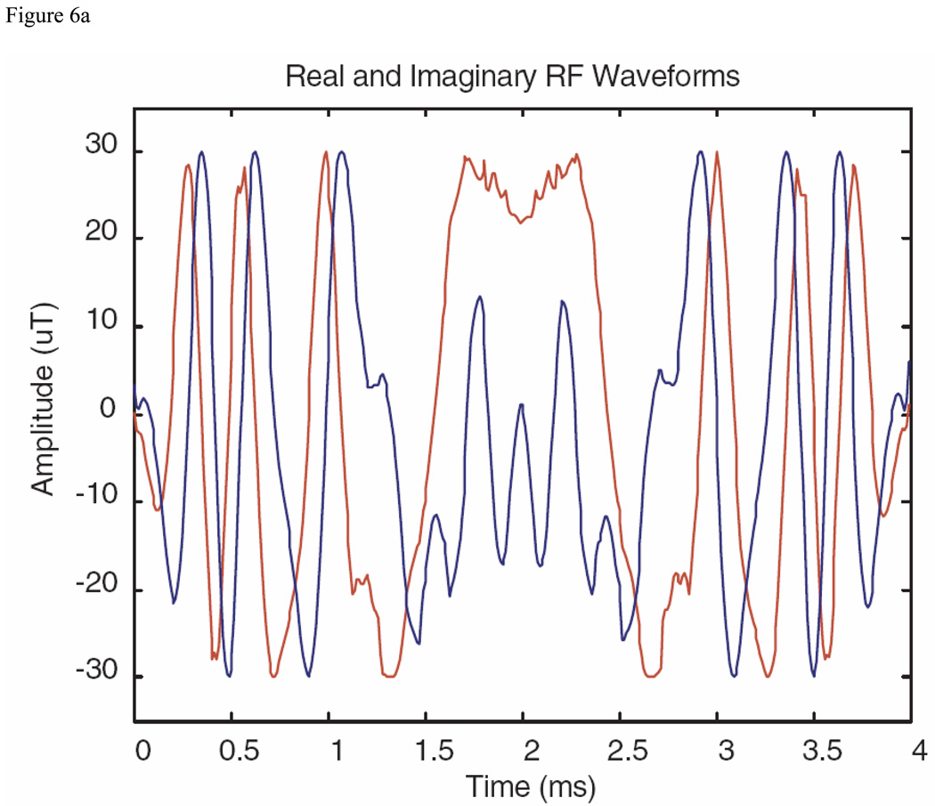
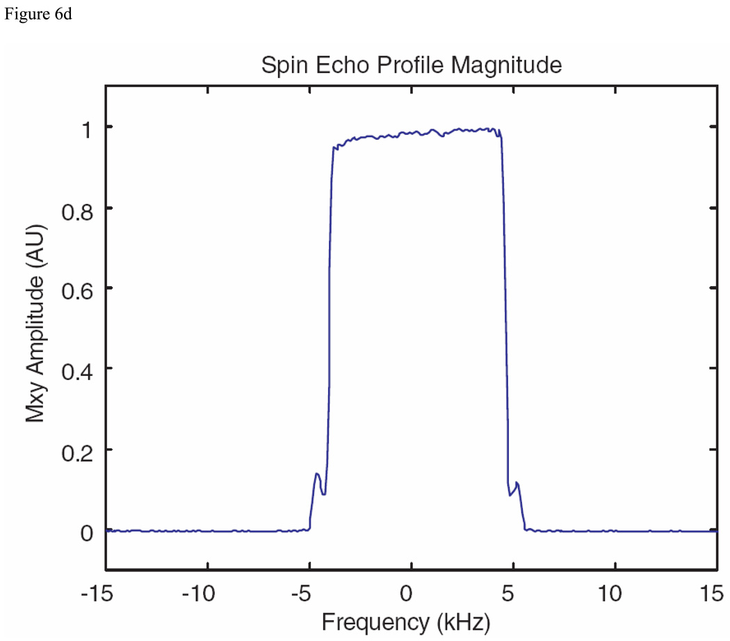
Initiating the MatPulse optimal control routine with a hyperbolic secant squared (HS2) pulse [4] and limiting B1max to 30 µT led to an inversion pulse with a bandwidth of 8 kHz, with the real and imaginary components of the pulse displayed in Fig. 6A, and the inversion profile (Mz) in Fig. 6B. Although immunity to B1 inhomogeneity was not requested in the optimal control routine, immunity to B1 inhomogeneity in excess of +/− 10% was nevertheless obtained. This pulse had both a substantially broader bandwidth and sharper transitions (approximately 20% transition regions) than could be achieved with the same length hyperbolic secant pulses raised to a power (HSn pulse). The use of a 6 ms long HS3 pulse, with a B1max of 30 µT and a µ of 20, did generate a similar profile (with a smooth transition band), but at the expense of a 50% longer pulse. An overlay of the HS3 profile with the optimal control inversion pulse profile is shown in red in Fig. 6C. An experimental profile for dual optimal control inversion pulses performing as a spin echo pulse (magnitude of crushed spin echo transverse magnetization) is shown in Fig. 6D.
Fig. 6.
Inversion pulse example with a bandwidth (at the bottom of the profile) of 8 kHz produced with the MatPulse optimal control routine, with a B1max of 30 µT. The pulse was initiated with a HS2 inversion pulse as described in the text. (A) Real and imaginary components of the optimized inversion pulse. (B) Bloch equations inversion (Mz) profile produced by the pulse. (C) Overlay of a 6 ms HS3 pulse inversion profile (red) with the optimized pulse profile. Additional details are supplied in the text. (D) Experimental crushed spin echo magnitude profile in arbitrary units (AU) of dual inversion pulses operating to create the spin echo. Additional details of the experimental profile are discussed in the text.
Discussion
We chose to compare our inversion pulse to the HSn style pulses, as the HSn pulse includes parameters to improve the bandwidth without increasing the B1max (n), and also improve the selectivity (µ). The bandwidth of 8 kHz is to be compared to a bandwidth of less than 6 kHz which we could achieve with similar pulse length HSn style pulses [4]. By lengthening the HSn style pulse (HS3) to 6 ms (50% longer than the inversion pulse example), we were able to generate a similar pulse profile as demonstrated in Fig. 6C. In addition, the pulses generated similar SAR. However, the increased HS3 pulse duration would also lengthen the minimum overall TE when dual pulses were used to generate a spin echo. Although the transition band for the inversion pulse example was approximately 20%, this was somewhat reduced in the spin echo profile due to the action of the
The optimal control inversion pulse provides improved performance in terms of bandwidth, given restrictions on B1max and pulse length, over our best efforts with an HSn pulse [14]. Although immunity to B1 inhomogeneity was not requested in the optimal control routine, immunity in excess of +/− 10% was nevertheless obtained. The pulse was designed with the idea that dual inversion pulses would be used to function as spin echo pulses in PRESS or LASER. As discussed above, the use of dual 4ms inversion pulses was much more efficient than the use of a single spin echo pulse, whose length might approach 20 ms [14]. The spikes in the transition regions are a result of not specifying the signal in the transition regions. However, the spike amplitudes are diminished in the experimental spin echo profile (Fig. 6D) due to the action of the dual pulses. While inclusion of points in the transition band resulted in smoother transition regions, it also resulted in diminished pulse performance (Results not shown).
iii) Saturation pulse example
Results
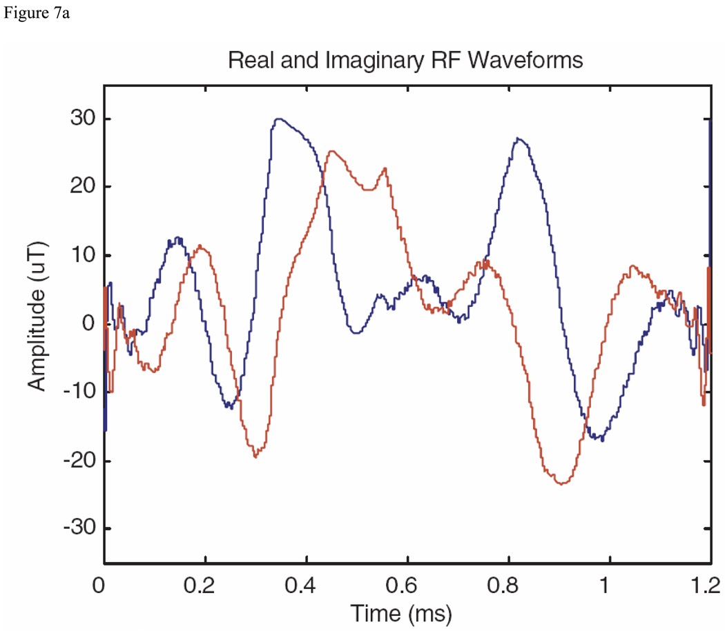
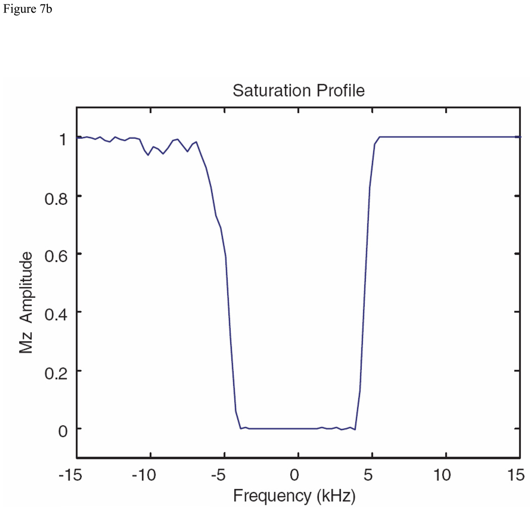
Because of the sensitivity of the S-P saturation pulses to B1 inhomogeneity (See Discussion), it was anticipated that the saturation pulses would be quite sensitive to B1 inhomogeneity, and two applications would be required to achieve the desired suppression. Therefore the shortest possible pulse was sought. To minimize the pulse length, the optimal control routine only requested a single side of the profile to be optimized. Starting with a hyperbolic secant shape and limiting B1max to 30 µT yielded the pulse shown in Fig 7A (real and imaginary components), with the saturation profile (Mz) displayed in Fig 7B. The width of the transition region was approximately 15%. An experimental magnitude (transverse magnetization) profile of the pulse acting as an excitation pulse in the PRESS sequence is shown in Fig. 7C.
Fig. 7.
Single-sided saturation pulse example with a bandwidth (at the bottom of the profile) of 8 kHz produced with the MatPulse optimal control routine, with a B1max of 30 µT. The pulse was initiated with a hyperbolic secant pulse as described in the text. (A) Real and imaginary components of the optimized single-sided saturation pulse. (B) Bloch equations saturation profile (Mz) produced by the pulse. (C) Experimental magnitude profile (transverse magnetization) in arbitrary units (AU) of the pulse operating as an excitation pulse. Additional details of the experimental profile are discussed in the text.
Discussion
As the comparison saturation pulse (Fig. 3) showed considerable sensitivity to B1 inhomogeneity (See above), it was assumed that dual saturation pulses would have to be applied to achieve the desired saturation in the presence of B1 inhomogeneity of +/− 5%,. Note that the ripples in the saturation (Fig.7B) average to zero, and would not be expected to degrade the overall saturation. The transition band of this pulse was approximately 15%. Similar pulses of the same overall length but with symmetrical rejection bandwidths had ripple amplitudes four to five times higher than the single-sided pulse shown. As expected, the saturation pulse exhibited similar sensitivity to B1 inhomogeneity as the comparison saturation pulse, with the error in magnetization approximately double the error in B1 (e.g., an error in B1 of 5% produced an error of approximately 7.5% in the Mz magnetization). Efforts to build in immunity to B1 inhomogeneity without substantial lengthening of the pulse or increasing its amplitude proved unsuccessful.
The ability of the optimal control method to request optimization over a single transition band (a single- sided pulse) enables the method to produce a shorter saturation pulse (for the same B1max and bandwidth) than is capable by the Schulte et al. method [14], which is constrained to symmetrical pulse profiles. As this pulse was designed to diminish the voxel size as described by references 5 and 6, a single-sided pulse was adequate for this purpose. As with the excitation pulse, the inversion and saturation pulse examples are scaleable, with longer pulses having proportionally lower B1max and reduced bandwidth.
Although the MatPulse frequency selective optimal control routine also contained options to specify the degree of immunity to B1 inhomogeneity, and to limit the SAR produced by the pulse, these options were not used for the frequency selective example pulses presented here. In addition, the routine allowed for inclusion of the profile transition regions in the optimization. However, as the inclusion of these points tended to reduce the pulse performance, the transition regions were left unspecified for the example pulses presented here.
3. Usage
i) Excitation and inversion pulses
We conclude that it is more efficient to make use of dual inversion pulses rather than a single spin echo pulse for broadband generation of spin echoes. On the other hand, the optimal control produced excitation and inversion pulses with rather similar performances (Compare Fig. 5 and Fig. 6). This suggests a hybrid localization experiment, in which the PRESS spin echo pulses are replaced by dual inversion pulses. This experiment, executed with the example excitation and inversion pulses, would retain some of the advantages of both the PRESS and LASER experiments. Such an experiment was run on a human head in our standard headcoil with our 4.0 T instrument with a repetition rate (TR) of 2.5 seconds without exceeding SAR limitations. However, this same experiment might well exceed SAR limitations at 7.0 T. As the pulses are scaleable, they could, for example, be lengthened to 6 ms, which would reduce the bandwidth to 5.3 kHz, and also reduce the B1max to 20 µT, yielding a SAR reduction of 1/3. Commercial 7.0 T MRI systems (GE, Siemens, Philips) use 7 or 8 kW RF amplifiers, so users of these systems find themselves restricted to a B1max of around 20 uT, and scaling of this order would be required even without SAR considerations.
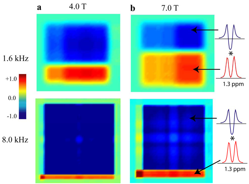
To further illustrate the advantages of the optimal control-designed pulses, we have included two-dimensional simulations of first, a PRESS-localized signal distribution of the lactate doublet at 1.3 ppm with 1.6 kHz bandwidth spin echo pulses at 4.0 T and 7.0 T, followed by the hybrid experiment localizing the doublet signal of lactate with 8 kHz bandwidth inversion pulses at 4.0 T and 7.0 T (Fig. 8). The 1.6 kHz bandwidth pulse represented the largest bandwidth spin echo pulse we could easily generate with the MatPulse root reflection scheme without exceeding 30 µT. All simulations were done with a TE of 46 ms, and simulations of the spectra at 7.0 T are included as well. The asterisk (*) denotes the spectral location (4 Hz wide) of the localized signal distribution used for generation of the color maps. The spectral simulations were done using the GAMMA [24] library with full density matrix computations, ideal initial excitation pulse, and the actual spin echo localization pulses. The simulations used 64 steps over the voxel in each direction to generate 4k spectra. The light banding seen in the simulations for the 8 kHz bandwidth pulses at 7T is due to the small ripples (approximately 0.3%) on the inversion pulses. Further details of the simulations can be found in reference 3.
Fig. 8.
Two-dimensional simulations of the localization of the lactate doublet at a TE of 46 ms at (a) 4.0 T, and (b) 7.0 T, demonstrating the different compartment sizes as a function of localization pulse bandwidth in the spin echo directions (1.6 kHz and 8.0 kHz). Spectra from two of the compartments are shown at 7.0 T. The asterisk (*) denotes the spectral location (4 Hz wide) of the localized signal distribution used for generation of the color maps. Additional details of the simulations are provided in the text.
ii) Saturation pulse
Despite the advantages of broadband localization, there may well be situations in which, in order to further limit SAR, or minimize TE, that the use of broadband localization pulses is not feasible. For these situations, one remedy is to use narrowband localization pulses to localize a larger region than desired, and eliminate the regions of anomalous phase by use of selective saturation pulses [5,6]. The short length of the demonstration saturation pulse (1.2 ms), coupled with the fact that it operates well below its B1max for most of its duration, means that its SAR is approximately 1/3 that of the excite demonstration pulse, and less than 1/7 that of the inversion demonstration pulse. In addition, the pulse may be re-scaled for further reduction of the SAR.
CONCLUSIONS
This article demonstrates the ability of optimal control methods to produce significant increases in bandwidth compared to conventionally designed frequency selective pulses of the same length and B1max. In addition, relatively sharp selection profiles were obtained (transition bands of 10% to 20%). More specifically, in comparison to an SLR-designed excitation pulse, a substantially increased bandwidth excitation pulse with linear phase was achieved. In addition, a significantly increased bandwidth inversion pulse (compared to an HSn style pulse [14]) with sharp selection profiles was achieved. Finally, due to the ability to specify a single-sided pulse with the optimal control method, a significantly shortened saturation pulse with sharp profiles was obtained. While comparable bandwidth for frequency selective spin echo pulses as achieved with sophisticated root reflection schemes [14] can be obtained with optimal control methods, we found that the use of dual inversion pulses for generation of a spin echo was the more efficient method to achieve our goal of 8 kHz bandwidths without exceeding a B1max of 30 uTesla.
In general, the price for increased bandwidth in selective excitation pulses is increased SAR. For the inversion pulse, the SAR was similar to the longer HS3 pulse producing a similar profile. In the example used for saturation, the price was primarily the loss of symmetrical selectivity (single-sided pulse). However, for the proposed purpose, symmetrical selectivity was unnecessary.
Although the optimal control routines incorporated into MatPulse also allowed for specified immunity to B1 inhomogeneity, this option was not used for these initial examples of the MatPulse optimal control routines for frequency selective pulses.
In summary, new frequency selective excitation, inversion, and saturation pulses obtained with the use of optimal control were demonstrated with significantly improved performance over previous designs. The excitation and inversion pulses had improved bandwidths, while the saturation pulse was achieved with a shorter duration pulse, and all pulses demonstrated excellent selectivity. The incorporation of the optimal control routines into MatPulse allowed for easy examination and further manipulation of the resulting pulses. The new pulse designs demonstrated here should prove useful for single voxel in vivo spectroscopy at high fields, especially for observation of J-coupled metabolites. However, the high SAR generated by the excitation and inversion pulses will undoubtedly limit their use in some circumstances.
A new version of MatPulse containing the optimal control routines and the example spectroscopy pulses is available for downloading at the CIND website: www.cind.research.va.gov/
Acknowledgements
We would like to thank Dr. Michael W. Weiner for his support of our research at the Center for Imaging of Neurodegenerative Diseases at the San Francisco VA Medical Center. This work was supported by NIH grants 5R01EB000766, and 1P41RR023953.
Appendix. The optimal control routine in MatPulse
The MatPulse broadband and frequency selective optimal control menus contained entries for the desired range of B1 immunity to be entered. For excitation pulses, a linear phase (phase proportional to frequency) could be chosen, along with a factor expressing the proportionality of phase to frequency (e.g., a factor of unity meant the phase was calculated as the frequency times the pulse length). The menus allowed RF pulses designed with MatPulse to be used as the initial sequence, and the resulting pulses to be examined and manipulated by the other MatPulse routines.
Both the broadband and frequency selective menus allowed for:
Loading of the initial pulse from another MatPulse routine
Selection of the pulse type (excite, saturate, invert, or spin echo)
Setting of the tip angle
Depending on the pulse type, selection of coalesced magnetization, non-coalesced magnetization, or linear phase (along with the linear phase factor)
The excitation bandwidth and number of points over the bandwidth
The B1 immunity range, and number of steps over this range The maximum B1 in µT
The initial step size ε
The tolerance for an increase in the residual as discussed above
A maximum iteration number
An option to try to minimize the specific absorption rate (SAR) produced by the pulse
An option to halt the iterations
In addition, the menus allowed the iterations to be halted by a targeted residual, or by a targeted differential residual, or to halt if the residual was increasing.
The frequency selective menu also allowed:
Setting of the rejection band and transition band widths, and the number of points over these bands
Selection of single-sided or symmetrical rejection band
Setting of the width of a Gaussian weighting that covered the excitation and rejection bands
The implementation of the transition region followed that of reference 8.
The relative weighting of pass band, rejection band, and transition band points was controlled by a combination of the number of points over the various bands, and the Gaussian weighting. For the pulses optimized in this article, the transition bands were left unspecified (zero transition band points) as the inclusion of points in the transition band tended to diminish the pulse performance. In addition, the option for SAR minimization was not used.
For saturation pulses, where the phase of the transverse magnetization did not matter, at each iteration the phase of the target transverse magnetization was set to that of M(tp) prior to computing the vector Lagrange multiplier‥ For the spin echo pulses, the algorithm required inversion of My and simultaneous retention of Mx [8].
Footnotes
Publisher's Disclaimer: This is a PDF file of an unedited manuscript that has been accepted for publication. As a service to our customers we are providing this early version of the manuscript. The manuscript will undergo copyediting, typesetting, and review of the resulting proof before it is published in its final citable form. Please note that during the production process errorsmaybe discovered which could affect the content, and all legal disclaimers that apply to the journal pertain.
References
- 1.Yablonskiy DA, Neil JJ, Raichle ME, Ackerman JJ. Homonuclear J coupling effects in volume localized NMR spectroscopy: pitfalls and solutions. Magn Reson Med. 1998;39:169–178. doi: 10.1002/mrm.1910390202. [DOI] [PubMed] [Google Scholar]
- 2.Maudsley AA, Govindaraju V, Young K, Aygula ZK, Pattany PM, Soher BJ, Matson GB. Numerical simulation of PRESS localized MR spectroscopy. J Magn Reson. 2005;173:54–63. doi: 10.1016/j.jmr.2004.11.018. [DOI] [PubMed] [Google Scholar]
- 3.Kaiser LG, Young K, Matson GB. Numerical simulations of localized high field 1H MR spectroscopy. J Magn Reson. 2008;195:67–75. doi: 10.1016/j.jmr.2008.08.010. [DOI] [PMC free article] [PubMed] [Google Scholar]
- 4.Garwood M, DelaBarre L. The return of the frequency sweep: designing adiabatic pulses for contemporary NMR. J Magn Reson. 2001;153:155–177. doi: 10.1006/jmre.2001.2340. [DOI] [PubMed] [Google Scholar]
- 5.Edden RA, Schar M, Hillis AE, Barker PB. Optimized detection of lactate at high fields using inner volume saturation. Magn Reson Med. 2006;56:912–917. doi: 10.1002/mrm.21030. [DOI] [PubMed] [Google Scholar]
- 6.Edden RA, Barker PB. Spatial effects in the detection of gamma-aminobutyric acid: improved sensitivity at high fields using inner volume saturation. Magn Reson Med. 2007;58:1276–1282. doi: 10.1002/mrm.21383. [DOI] [PubMed] [Google Scholar]
- 7.Murdoch JB, Lent AH, Kritzer MR. Computer-optimized narrowband pulses for multislice imaging. J Magn Reson. 1987;74:226–263. [Google Scholar]
- 8.Conolly S, Nishimura D, Macovski A. Optimal control solutions to the magnetic resonance selective excitation problem. IEEE Trans Med Imaging. 1986;2:106–115. doi: 10.1109/TMI.1986.4307754. [DOI] [PubMed] [Google Scholar]
- 9.Mao J, Mareci TH, Scott KN, Andrew ER. Selective inversion radiofrequency pulses by optimal control. J Magn Reson. 1986;70:310–318. [Google Scholar]
- 10.Rosenfeld D, Zur Y. Design of adiabatic selective pulses using optimal control theory. Magn Reson Med. 1996;36:401–409. doi: 10.1002/mrm.1910360311. [DOI] [PubMed] [Google Scholar]
- 11.Pauly J, Roux PLe, Nishimura D, Macovski A. Parameter relations for the Shinnar-Le Roux selective excitation pulse design algorithm. IEEE Trans Med Imaging. 1991;10:53–65. doi: 10.1109/42.75611. [DOI] [PubMed] [Google Scholar]
- 12.Tannus A, Garwood M. Adiabatic pulses. NMR Biomed. 1997;10:423–434. doi: 10.1002/(sici)1099-1492(199712)10:8<423::aid-nbm488>3.0.co;2-x. [DOI] [PubMed] [Google Scholar]
- 13.Roux PLe, Gilles RJ, McKinnon GC, Carlier PG. Optimized outer volume suppression for single- shot fast spin-echo cardiac imaging. J Magn Reson Imaging. 1998;8:1022–1032. doi: 10.1002/jmri.1880080505. [DOI] [PubMed] [Google Scholar]
- 14.Schulte RF, Roux PLe, Vogel MW, Koenig H. Design of phase-modulated broadband refocusing pulses. J Magn Reson. 2008;190:271–279. doi: 10.1016/j.jmr.2007.11.008. [DOI] [PubMed] [Google Scholar]
- 15.Skinner TE, Reiss TO, Luy B, Khaneja N, Glaser SJ. Reducing the duration of broadband excitation pulses using optimal control with limited RF amplitude. J Magn Reson. 2004;167:68–74. doi: 10.1016/j.jmr.2003.12.001. [DOI] [PubMed] [Google Scholar]
- 16.Kobzar K, Skinner TE, Khaneja N, Glaser SJ, Luy B. Exploring the limits of broadband excitation and inversion pulses. J Magn Reson. 2004;170:236–243. doi: 10.1016/j.jmr.2004.06.017. [DOI] [PubMed] [Google Scholar]
- 17.Skinner TE, Reiss TO, Luy B, Khaneja N, Glaser SJ. Application of optimal control theory to the design of broadband excitation pulses for high-resolution NMR. J Magn Reson. 2003;163:8–15. doi: 10.1016/s1090-7807(03)00153-8. [DOI] [PubMed] [Google Scholar]
- 18.Gershenzon NI, Kobzar K, Luy B, Glaser SJ, Skinner TE. Optimal control design of excitation pulses that accommodate relaxation. J Magn Reson. 2007;188:330–336. doi: 10.1016/j.jmr.2007.08.007. [DOI] [PubMed] [Google Scholar]
- 19.Luy B, Kobzar K, Skinner TE, Khaneja N, Glaser SJ. Construction of universal rotations from point-to-point transformations. J Magn Reson. 2005;176:179–186. doi: 10.1016/j.jmr.2005.06.002. [DOI] [PubMed] [Google Scholar]
- 20.Kobzar K, Luy B, Khaneja N, Glaser SJ. Pattern pulses: design of arbitrary excitation profiles as a function of pulse amplitude and offset. J Magn Reson. 2005;173:229–235. doi: 10.1016/j.jmr.2004.12.005. [DOI] [PubMed] [Google Scholar]
- 21.Gershenzon NI, Skinner TE, Brutscher B, Khaneja N, Nimbalkar M, Luy B, Glaser SJ. Linear phase slope in pulse design: application to coherence transfer. J Magn Reson. 2008;192:235–243. doi: 10.1016/j.jmr.2008.02.021. [DOI] [PubMed] [Google Scholar]
- 22.Schulte RF, Henning A, Tsao J, Boesiger P, Pruessmann KP. Design of broadband RF pulses with polynomial-phase response. J Magn Reson. 2007;186:167–175. doi: 10.1016/j.jmr.2007.02.004. [DOI] [PubMed] [Google Scholar]
- 23.Matson GB. An integrated program for amplitude-modulated RF pulse generation and re-mapping with shaped gradients. Magn Reson Imaging. 1994;12:1205–1225. doi: 10.1016/0730-725x(94)90086-7. [DOI] [PubMed] [Google Scholar]
- 24.Smith SA, Levante TO, Meier BH, Ernst RR. Computer Simulations in magnetic resonance. An object-oriented programming approach. J Magn Reson. 1994;106:75–105. [Google Scholar]


