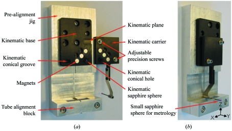
Figure 3.
Kinematic mounting of the mini-beam collimator. (a) Assembled mini-beam collimator on an exchangeable kinematic carrier, with the halves of the black-anodized Al kinematic mount separated showing details of the mount. The kinematic base is attached to an alignment jig. (b) Mini-beam apparatus mounted on the alignment jig. The two halves of the kinematic mount are mated. The bullet-shaped scatter guard and forward-scatter guard tube of the collimator are positioning in the alignment groves. The small sapphire ball at the end of the forward-scatter guard tube was attached only during metrology measurements. The pinhole and back-scatter guard are not shown.

