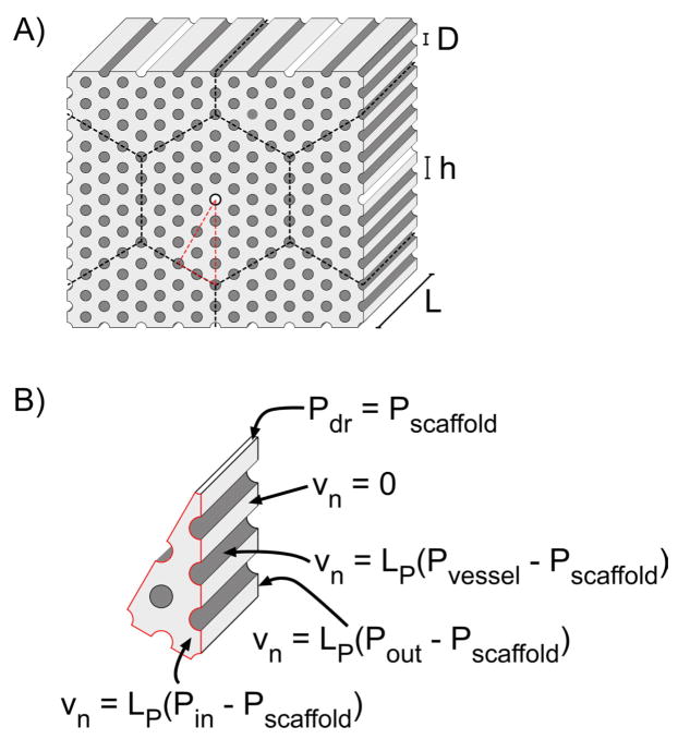
Figure 1.
Representative geometries of the tissue slab and computational domain, for the case of N = 4. A) Front and back faces of the tissue slab are separated by a distance L. Vessels of diameter D form a hexagonal lattice of spacing h. Cylinders with white and dark grey walls represent drainage channels and vessels, respectively. Dashed black lines denote planes of symmetry. Dashed red lines outline the actual computational domain. B) Boundary conditions on the scaffold and their regions of applicability.

