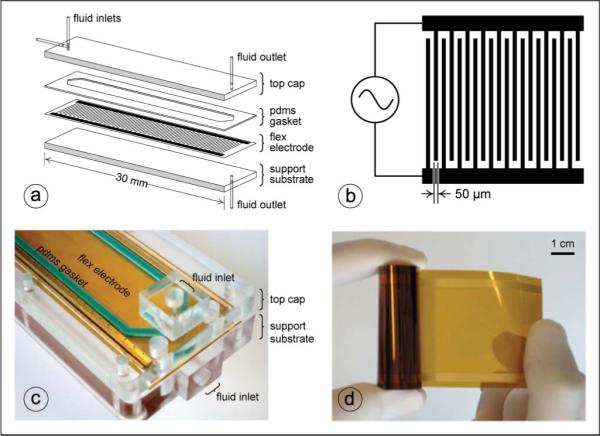
Fig. 2.

DEP-FFF instrumentation. (a) Exploded diagram of DEP-FFF separator chamber showing support and top substrates, flex electrode, PDMS gasket, and fluid ports. (b) Schematic of interdigitated electrode array (not to scale). (c) Close-up of inlet portion of assembled stacked-polymer DEP-FFF separator chamber showing support and top substrates, flex electrode, PDMS gasket, and fluid ports. (d) Continuous flex-circuit reel of 50 μm-wide gold microelectrodes on polyimide substrate.
