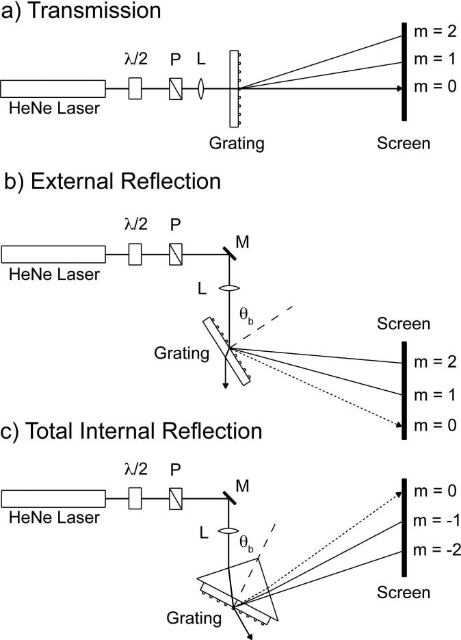
Figure 3.
Schematic diagram of the three geometries used to obtain diffraction images. In all cases the source is a HeNe laser with a polarizer (P) and a λ/2 plate to control the intensity and final polarization, and a lens (L) t20 focus the image on the screen. a) In Transmission geometry the laser impinges normal to the surface. b) In External reflection and c) Total internal reflection geometry the laser impinges at Brewster's angle (θb) for an air-glass and glass-air interface respectively.

