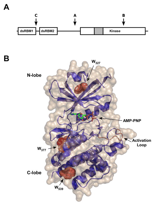
Figure 1.
PKR structure. A: Schematic representation of PKR domain organization. The letters “A,B,C” refer to the principal trypsin cleavage sites. The grey portion of the kinase domain corresponds to the kinase insert region. B: Structure of PKR kinase domain. The protein backbone is shown as a ribbon diagram in blue with the activation loop in brown. The three tryptophan side chains are shown in Van der Waals representation in red and AMPPNP is drawn in stick format. The solvent accessible surface is beige. The coordinates (PDB 2A19) were obtained from the crystal structure of a complex of the PKR kinase domain with eIF2α and AMPPNP (11) and the figure was rendered with PYMOL (Delano Scientific, Palo Alto, CA).

