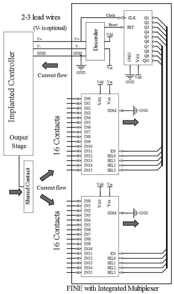
Fig 1.
Block diagram of the FINE with integrated circuit and the connection to a separate controller. The stimulation current is generated at the implanted controller, passed through the shared contact, an active channel of MUX and returned to GND. For the single supply design, V− is eliminated and Vss is connected to GND, reducing the number of wires to control the thirty-two channel multiplexer to only 2.

