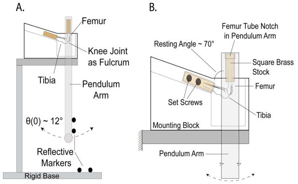
Figure 1.
Figure 1A. Schematic of simple pendulum system used for amplitude decay data collection. The pendulum arm was fixed to the proximal end of the femur and the tibia was rigidly mounted to a base platform. Four reflective markers were attached to both the pendulum arm and to the base (not all markers shown) for 3-D motion tracking. The arm was set to an initial angle of ~12°, released, and allowed to oscillate freely until damping out completely. B. Close-up schematic of the knee joint mount. Both limbs were embedded in square 6.25 mm tubing with a urethane-potting compound and secured into the apparatus at a resting angle of 70°. The tibia was fixed to the base with four set screws (two on each side of the limb). The proximal end of the tube-fitted femur fit into a square notch cut into the pendulum arm.

