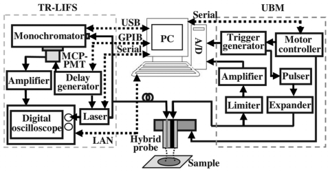
Figure 2.
Electronics and interfacing setup of the combined TR-LIFS∕UBM system. The schematic for the electronics configuration was designed to ensure proper synchronization of various components and automation of the data acquisition and analysis process. The interfaces (dashed lines) between the control unit and subsystems integrated the TR-LIFS and UBM into one functional system.

