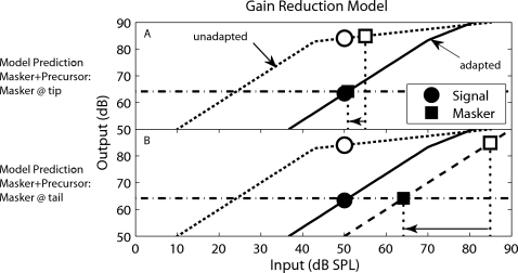
Figure 5.
Schematic representation of the gain-reduction model. This model assumed the on-frequency precursor reduced BM gain (or equivalently “adapted” the on-frequency I∕O function). Two masker frequencies are schematized, one at the same frequency as the signal (a) and the other far below the signal frequency (b). Within each panel, the masker (squares) and signal (circles) are plotted for the masker alone condition (open symbols), or for the masker+precursor condition (closed symbols). Notice that the masker alone condition assumes that the signal and on-frequency masker operate on the unadapted I∕O function [BMunadapted(in), dotted lines], while the masker+precursor condition assumes that the signal and on-frequency masker operate on the adapted I∕O function [BMadapted(in), solid lines]. The dashed line in (b) represents the linear I∕O function for the off-frequency masker. The horizontal line represents the masker output needed to maintain a constant signal-to-masker ratio at the output of the adapted I∕O function.

