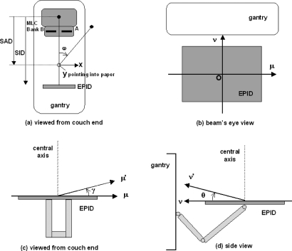
Figure 1.
Coordinate systems describing the imaging geometry of the EPID. (a) Isocentric plane (x,y) and gantry angle ω as viewed from the couch end. (b) EPID (μ,ν) plane as viewed in the beam’s eye view. (c) EPID’s μ-axis tilt γ as viewed from the couch end. (d) EPID’s ν-axis tilt θ as viewed from the side. SAD: Source-to-axis distance; SID: Source-to-imager distance.

