
Figure 5.
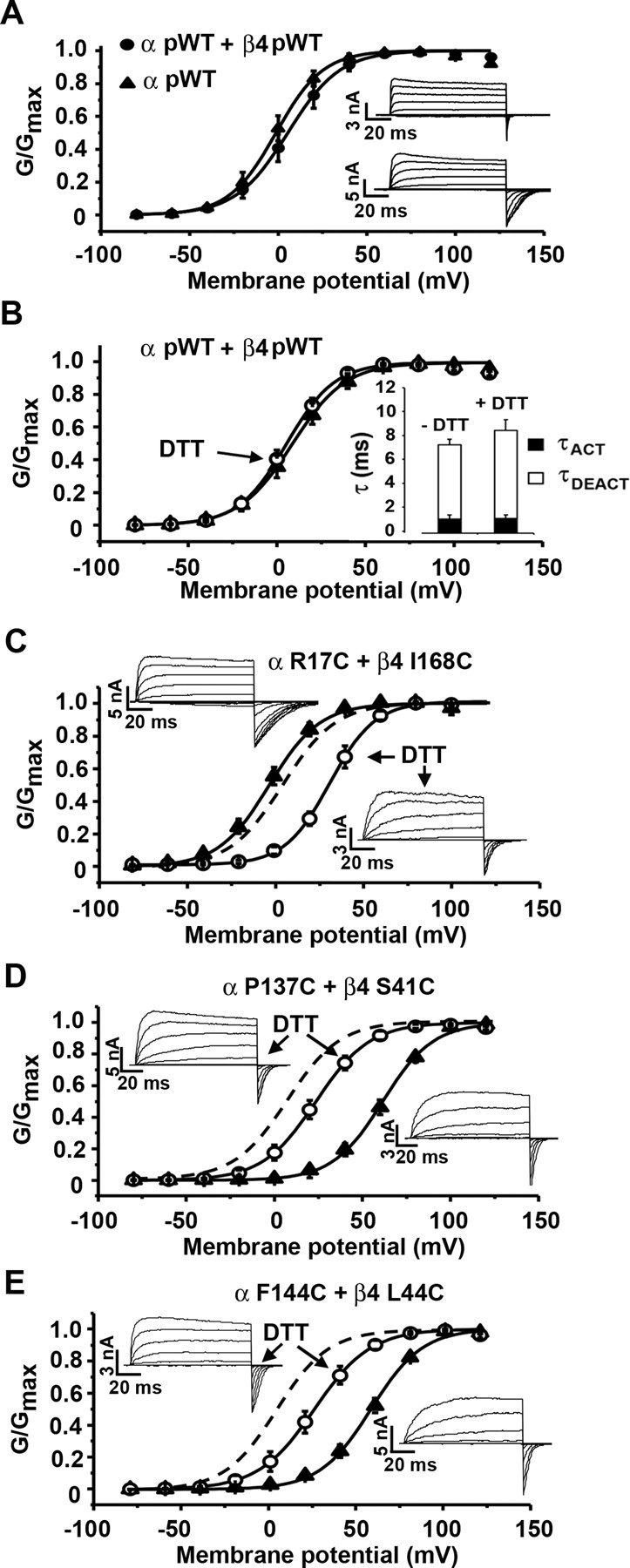
Activation, deactivation, and conductance–voltage curves for pWT and mutant channels. A, Normalized conductance as a function of voltage (G–V curve) for pWT α (filled triangles) and pWT α and pWT β4 (filled circles). The recordings were made in outside-out macropatches with 10 μm Ca2+ inside the pipette. Inset, Macroscopic currents conducted by pWT α (top) and pWT α and pWT β4 (bottom) in response to step depolarizations from −80 to +140 mV. B, G–V curve for pWT α + pWT β4 before (filled triangle) and after 20 mm DTT (open circle). Inset, Graph showing τACT and τDEACT in absence and presence of DTT. C–E, Macroscopic currents and G–V curves were determined with 10 μm Ca2+ inside the pipette before (filled triangles) and after (open circles) DTT for α R17C and β4 I168C (C), α P137C and β4 S41C (D), and α F144C and β4 L44C (E). Dashed lines represent the G–V curve for pWT α and pWT β4. Error bars are SD.