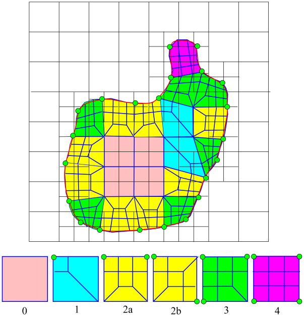
Fig. 8.
Top row - an example of adaptive quad mesh generation in 2D. Each green point represents a minimizer point of a cell to be refined, and the red curve represents the real isocontour. Bottom row - the decomposition templates of Method 3 shown in Figure 4.

