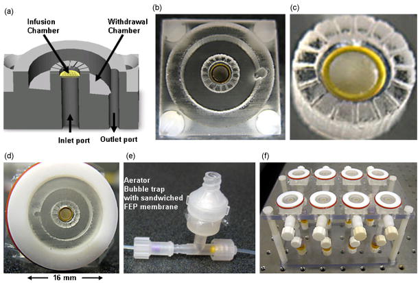
Figure 2.
The microperfusion chamber. (a) A 3D drawing of the device, showing an inner (culture) chamber, an outer (withdrawal) chamber, and inlet and outlet ports. (b) Device fabricated in PDMS. (c) Magnified view of the culture chamber. A porous substrate (gold grid) at the bottom of the chamber delivers the nutrient medium to the tissue. Tissue is sealed to the chamber via an adhesive layer of laminin. The cylindrical enclosure contains 350μm deep microchannels starting mid-height through the culture chamber to facilitate the outflow of media from the culture into the withdrawal chamber. (d) A microperfusion chamber encapsulated by a semi-permeable membrane in a Teflon lid. A substantially gas permeable, and substantially water and water vapor impermeable (fluorinated ethylene-propylene, FEP) membrane is stretched over the Teflon lid using O-rings. The membrane maintains asepsis, facilitates gas exchange, prevents tissue desiccation, and equilibrates the medium contained within the culture chamber. (e) An in-line aerator/bubble trap placed in the infusion circuit. It is a two-piece device sandwiching an FEP membrane. This device serves to equilibrate the medium with the incubator environment just prior to injection into the culture chamber. It also removes gas bubbles from the medium and damps fluctuations in liquid delivery. (f) A custom fabricated Plexiglas stand to support a plurality of perfusion chambers for parallel experimentation. This stand eases the sterile transfer of experimental set-up from the laminar flow-hood into the incubator.

