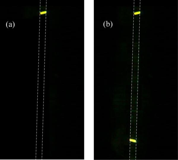
Figure 9.

(a) Fluorescence image of the microfluidic channel with intersecting optical waveguides and containing Ab* and Ab sites grafted inside the channel by μCP, following rinsing but prior to the introduction of the fluorescent antigen (Ab invisible). Channel walls are indicated as a dotted line. The grafted Ab* control pattern is visible in front of the Y-junction’s upper waveguide. (b) Fluorescence image of the same microfluidic channel following introduction of the fluorescent antigen and rinsing. The Ab/Ag* complex positioned in fromt of the Y-junction’s lower waveguide is now visible (fluorescent BXFM Olympus microscope with a 100 mW doubled YAG laser excitation source).
