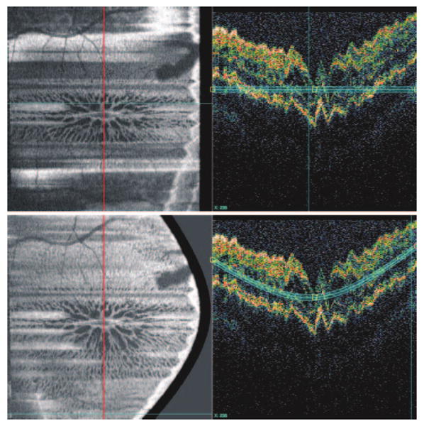
Figure 5.

Switching to a vertical section (along the red line, left), the C-mode image (top) stays the same as the C-mode image from Figure 4 (bottom) because no contour modeling on the vertical section has been performed. Note the jagged contour on the vertical section caused by eye motion along z-axis during imaging. After adjusting three anchor locations in a single B-mode tomogram (bottom right), most of the horizontal artifact on the C-mode image is resolved (bottom left).
