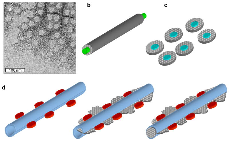
Figure 11.
Central templating vs. confinement model for mesoscale structure formation. (a) TEM image of the silicification front during valve formation in T. pseudonana. Note the branched silica structure, and the location of regions where pores are forming, which lack silica. Image is in the same region as Fig. 3c in (Hildebrand et al., 2006), but is a distinct image. (b) Central templating model involving a linear protein (green) around which silica (gray) is deposited to form a rod structure. (c) Central templating model involving droplets of polyamines (blue) around which silica (gray) is deposited. In both models, the initial deposition of silica is concentrated around the template. (d) Confinement model of silicification. On left are depicted organic complexes comprising pores (in red) which flank a tubular structure (light blue) made of organics in the SDV lumen. Center depicts the initial stage of deposition, where silica is not yet confined, but forms a flat sheet within the tubule and between the pores. On the right, silica becomes concentrated in the tubule, and is less dense in the pore region. In this model, silica is initially not concentrated in one area, but becomes so over time.

