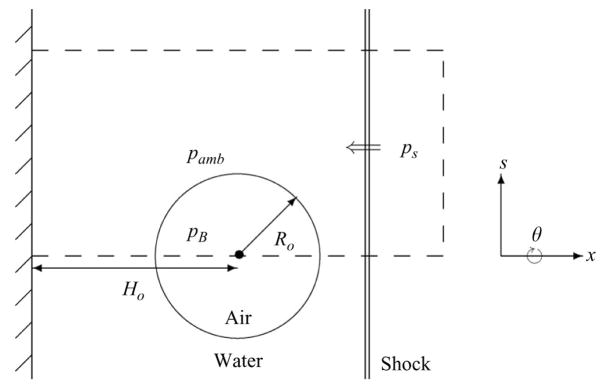
Figure 1.
Schematic of the problem geometry (not to scale). The dashed line indicates the computational domain, which is a cylinder revolved about the axis s = 0. In the case of collapse near a wall, the left boundary of the domain consists of a rigid wall (solid hatched line), and the double line on the right of the bubble denotes a shock.

