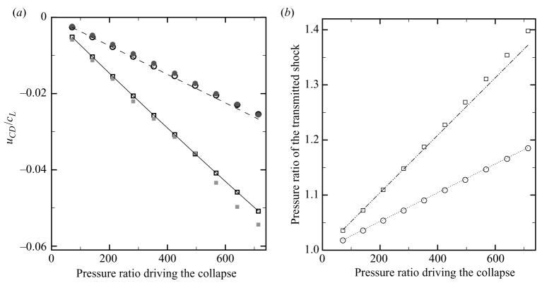
Figure 7.
Initial interface velocity, and pressure ratio across the transmitted shock as a function of the pressure ratio driving the collapse for shock-induced (squares) and Rayleigh (circles) collapse. The open symbols denote the analytical solution to the corresponding planar Riemann problem and the filled symbols refer to the simulations. (a) Initial interface velocity. Dashed line: (3.2); solid line: (3.3). (b) Pressure ratio across the transmitted shock. Dotted line: 1 + αz; dashed-dotted line: 1 + 2αz.

