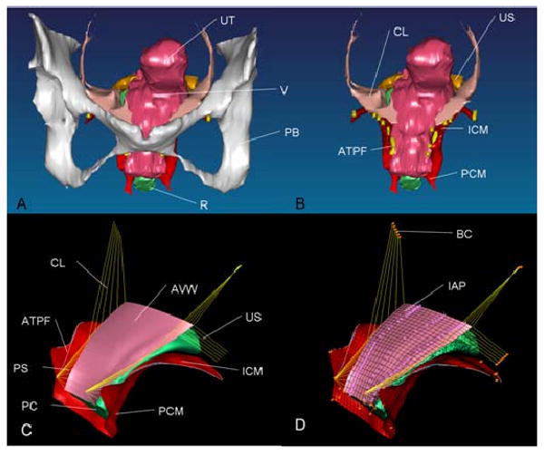
Figure 1.

Model development. A: 3D volume-rendered model of anterior support system including pubic bone; B: 3D volume-rendered model without pubic bone; C: Geometrically simplified surface model; D: 3D finite element model with mesh, boundary condition (orange pin representing ligaments and muscle origin is fixed to pubic bone and pelvic sidewall), and abdominal pressure loading. PB denotes pubic bone; UT: uterus (not included in surface model); V: vagina; R: rectum; CL: cardinal ligament; US: uterosacral ligament; ATFP: arcus tendineus fascia pelvis; ICM: iliococcygeus muscle; PCM: pubococcygeus muscle; AVW: anterior vaginal wall; PC: posterior compartment; PS: paravaginal support; and IAP: abdominal pressure
