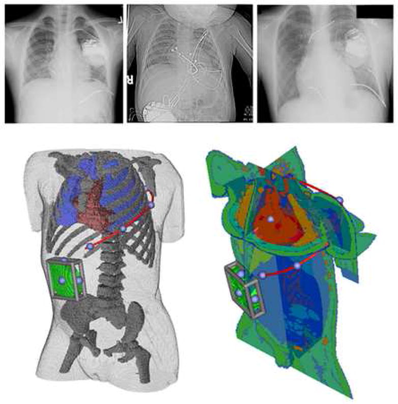
Figure 1. A. Examples of nonstandard subcutaneous, epicardial and transvenous electrode orientations.

Left: Infraclavicular can with single subcutaneous electrode, Middle: Abdominal can with epicardial lead, Right: Infraclavicular can with SVC and RV transvenous electrode as well as left subcutaneous electrode. B. User interface for electrode placement. A subcutaneous electrode (red) extending left posterior with right abdominal can (green) is shown in two year old torso shown in two views used while placing electrodes in finite element model. Moveable cutting planes allow the user to examine anatomical detail during electrode placement. The blue spheres on the red electrode and bounding cage on the can indicate handles for user interaction. Electrodes can be placed with similar precision in epicardial and transvenous orientations.
