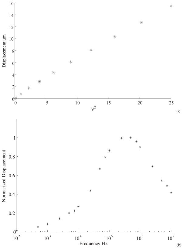
Figure 6.
(a) Actuator displacement was found to vary linearly with the square of applied voltage. The actuator was operated in DI water with a square signal at 1MHz frequency. The voltage axis denotes the RMS value. (b) Actuator displacement at constant RMS of 3.5 V plotted as a function of frequency. The plots are normalized to the maximum displacement of 8 μm.

