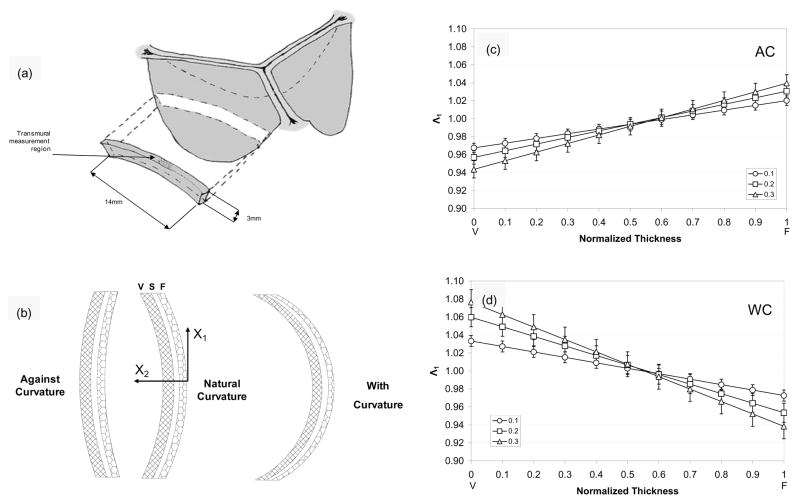
Figure 7.
Schematic showing (a) the orientation of the AV leaflet specimen used for flexural testing, including the location of the transmural measurement region, which was flexed in two directions to alternately subject the tissue layers to tension/compression (b)? The resulting transmural strain distribution of Λ1 with increasing curvature along the normalized thickness (V=ventricularis and F=fibrosa) for the (c) AC and (b) WC directions. Here, the intersection of the composite plots with Λ1 of 1 determined the location of the neutral axis, which was near the center and not dependent of flexural direction.

