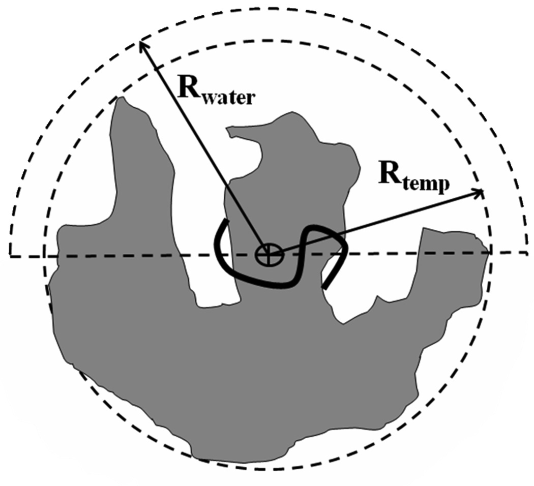
Figure 1.
A two dimensional diagram of the template and the spherical water restraining region. The loop is represented as the heavy black curve, where the symbol, ⊗, denotes xcmb - the center of mass of the loop backbone. xcmb is the center of the dashed (inner) circle (of radius = Rtmpl) which defines the edge of the (gray) template. xcmb is also the center of the larger (dashed) sphere of radius Rwater = Rtmpl+1 Å, where only the outer hemisphere of this sphere is shown. ~30 crystal water molecules are inserted into the template while the positions of the other waters are determined at random within the hemisphere. In the energy minimization and MD simulations the waters are restricted to the hemisphere by strong harmonic potentials. “Drifting” of water molecules to the “back” of the template through the sides is mostly avoided because Rwater is only 1 Å larger than Rtmpl.

