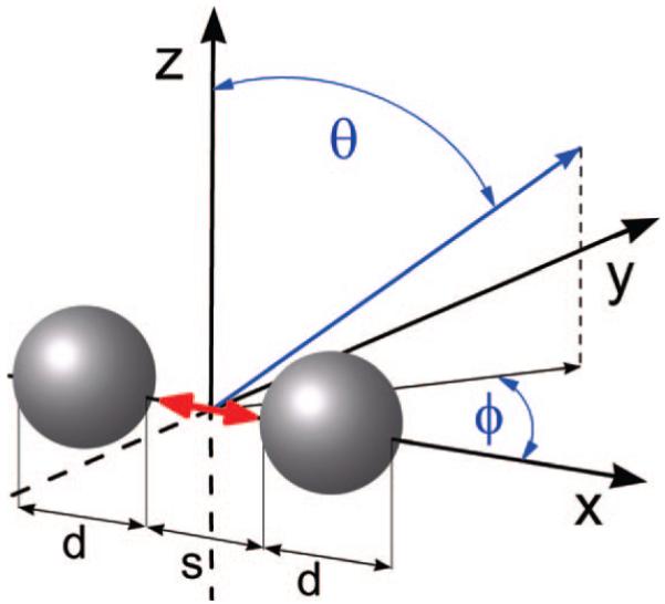
Figure 1.

Schematic diagram of the model radiating fluorophore/metal nanoparticle system studied. The red arrow represents the fluorophore, in the systems investigated, the fluorophores will be oriented along either the x or y axes, d is the diameter of the silver nanoparticle, s is the surface to surface distance between dimers (and in the case of the monomerssthe space between the fluorophore and the surface of the particle), θ is the polar angle from the z-axis, where 0 ≤ θ ≤ π, and Φ is the azimuthal angle in the x-y plane from the x-axis with 0 ≤ Φ < 2π.
