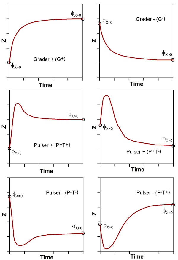
Figure 6.
Qualitative representation of all possible timecourse responses realized by FFLs. Here, 'G' indicates grader and 'P' pulser response of the circuit. The initial slope is represented by '+' or '-' in our nomenclature. The difference of the initial versus the target concentration is denoted as 'T +' or 'T-'.

