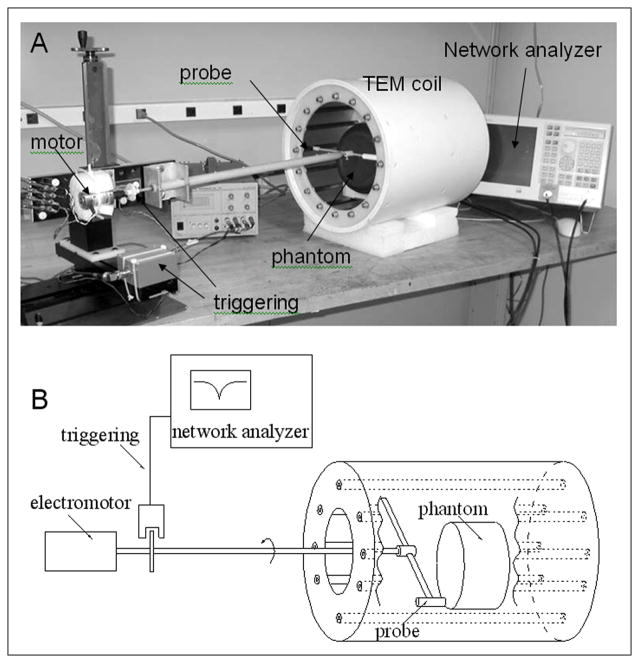
Figure 2.
A) Picture and B) block-diagram of the TEM coil tuning method. A ferrite probe rotated in close proximity to TEM elements to produce a shift of the resonance frequency and modulate S11. To visualize the modulation of S11, which reflects the current distribution in the TEM elements, the network analyzer was used in the linear amplitude mode with the frequency sweep turned off. The network analyzer was externally triggered from the rotation of the probe.

