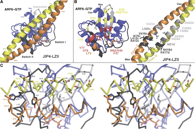
Figure 4.
The ARF6–JIP4-LZII interaction surface. (A) An overall view of the ARF6–JIP4-LZII interface. (B) An ‘open book' representation of the ARF6–JIP4 interface. Residues involved in the complex interface are labelled and shown as sticks. For ARF6, the residues that interact with chains C and D of JIP4 are shown, respectively, in orange and yellow; residues that interact with both chains are shown in red. For JIP4-LZII, residues that interact with the switch II and interswitch regions are shown, respectively, in light and dark grey; residues that interact with both are shown in mid grey. (C) Cross-eye stereo view of the interface. All the residues from ARF6 and JIP4-LZII that are involved in the interface are labelled and shown as sticks.

