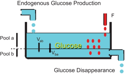
FIG. 1.
Schematic diagram illustrating the multiple-pool concept in tracer dilution studies. Pool a represents the readily accessible pool in which tracer distributes rapidly, in contrast to the less readily accessible pool (Pool b). The relative size of each pool can be altered by experimental (or physiological) conditions, as can the flow of tracer (and tracee) from Pool a to b (Vab) and vice versa (Vba). F, tracer infusion rate.

