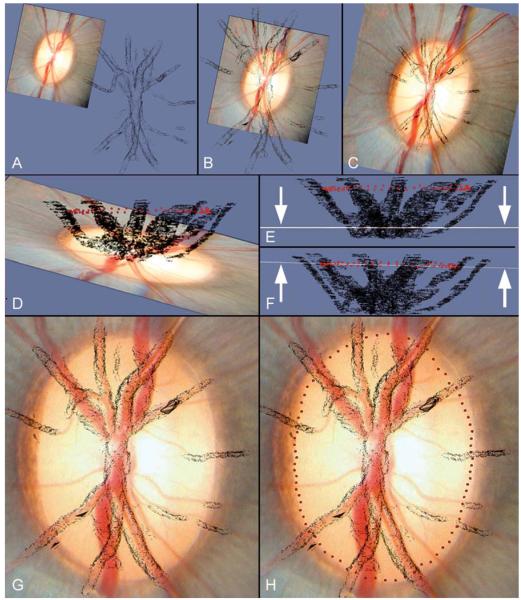
The clinical photograph is viewed prior to co-localization at a distance from the vessel reconstruction
X- and Y- axis shifts allow an approximate co-localization in the horizontal plane
The magnification of the clinical image has been increased to match the dimensions of the vessel reconstruction
The clinical photograph and vessel reconstruction are viewed in the coronal plane, with the BMO point cloud visible (red glyphs). This maneuver is performed to facilitate Z-axis adjustment. In this panel, the clinical photograph can be seen to be tilted in a different orientation to the long axis of the BMO point cloud
The Z-axis tilt has been adjusted so that the clinical image (seen in coronal profile, highlighted by arrows) is now orientated in the same plane as the long axis of the BMO point cloud
The clinical image has been moved vertically in the Z-axis so that the coronal image profile (highlighted by arrows) coincides with the BMO point cloud. Once this adjustment has been completed, the BMO points are switched off.
The clinical image is now viewed in the en-face orientation following z-axis adjustment. A rotation about the image centroid has been performed to accurately align the clinical vessel outline to the vessel reconstruction
The final location of the BMO points in relation to the clinical disc photograph is displayed

