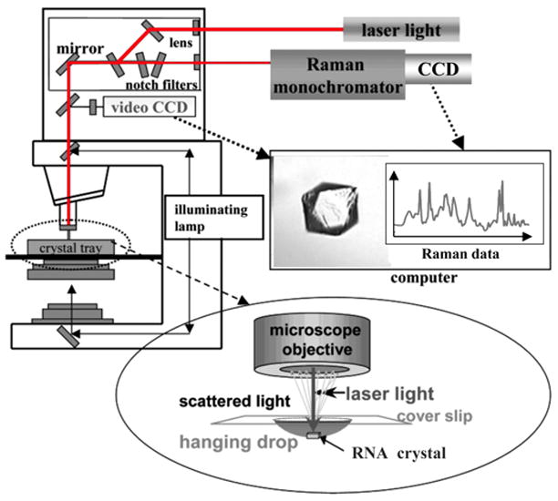
Fig. 1.

Diagram of the Raman microscope setup. Red laser light at 647 nm from a krypton ion laser (Coherent Innova 70C) is used to excite the RNA (follow red lines in diagram). The laser travels through a fiber optic cable to the top of a HoloLab Raman microscope. From there it moves through a series of lenses and mirrors and then impinges on an RNA crystal in a 5 L hanging drop in a crystal tray (see blow-up at bottom). The Raman photons that are backscattered from the crystal are collected through a microscope objective set to 50× and directed to a high-throughput Raman spectrograph with a CCD detector, which records the Raman data (see spectrum in red). To remove the intense Rayleigh scattering, this output travels through a series of notch filters prior to arriving at the monochromator. An illuminating lamp (follow black lines in diagram) allows the crystal to be visualized through a video CCD (see crystal of HDV ribozyme). This feature facilitates positioning of the crystal in the center of the laser beam by use of a microscope stage. Adapted with permission from [73]. (Copyright, American Chemical Society.)
