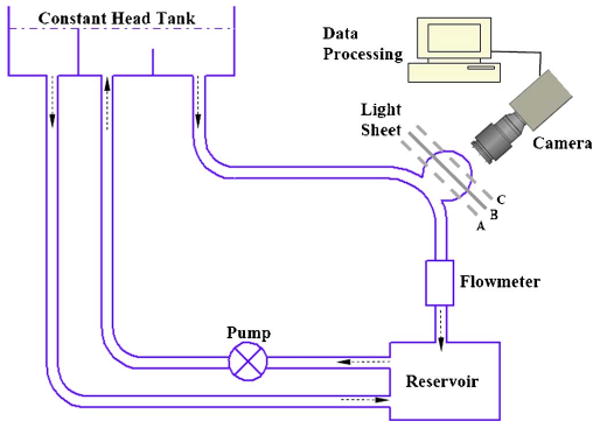
Fig. 2.

Schematic diagram of the experimental setup, with Plane B being imaged. Imaging Planes A and C required parallel shifts of the laser light sheet, and imaging Plane Z required turning the model block 90° so that the meridian plane faced the camera.
