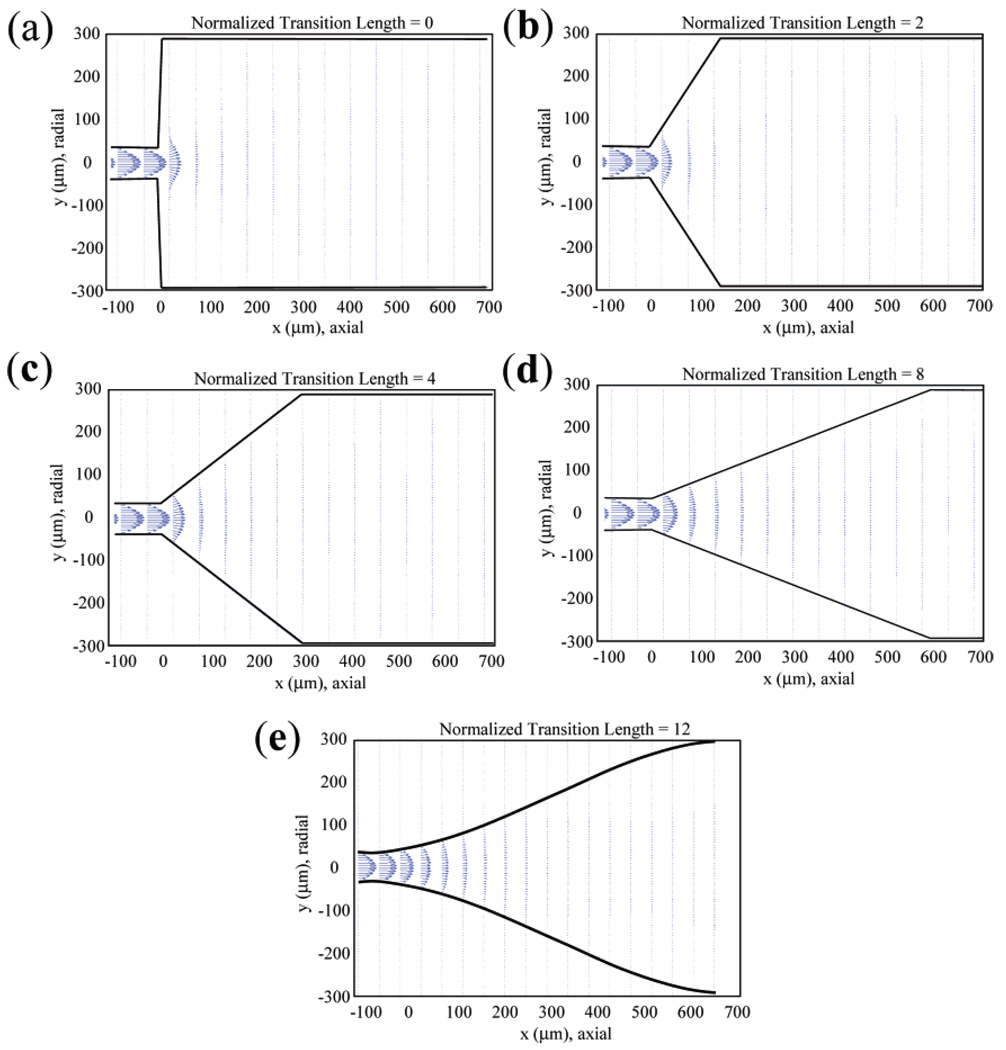
Figure 2.
Simulated velocity fields for flow cell geometries with different normalized transition lengths. (a–d) Normalized transition lengths of 0, 2, 4, and 8, respectively. (e) Normalized transition lengths of 12 used in the experimental studies. The velocities are represented as vectors, with both magnitude and direction indicated by the arrows.

