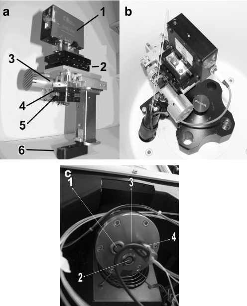
Fig. 2.
a Photograph of the detector arm: 1 Spectrometer; 2 Table with the possibility of x–y movement; 3 Step motor; 4 Lens (40-mm biconvex); 5 Iris and 6 90° Quartz prism. b The arm fitted in the centrifuge. c Photograph of the vacuum feedthrough: 1 Electronic feedthrough for step motor; 2 Electronic feedthrough for spectrometer; 3 Electronic connection for TTL pulse for rpm measurements; 4 Optical feedthrough for fibers

