
Fig. 12.
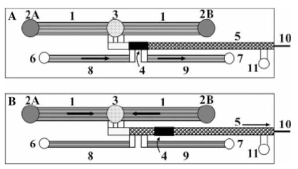
Schematic representation of a microfluidic LC system. 1 Pumping channels; 2A, 2B eluent inlet reservoirs; 3 eluent outlet reservoir; 4 double-T injector that contains the sample plug; 5 separation channel; 6 sample reservoir; 7 sample waste reservoir; 8 sample inlet channels; 9 sample outlet channels; 10 ESI capillary emitter; 11 LC waste reservoir. a Sample loading; b sample analysis. Arrows indicate the main flow pattern through the system. Reprinted with permission from Lazar et al. 2006