
Fig. 8.
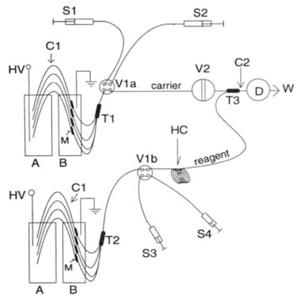
Schematic diagram of two-line FIA system with EOF pumping: B, pump electrolyte solution container; T1, T2, capillary unions; Vla and Vlb, four-way valve stacks a and b; S1 and S3, syringes holding pump buffer solution; S2 and S4, syringes respectively holding carrier and reagent solutions; HC, reagent holding coil; T3, low-volume tee union. Reprinted with permission from Dasgupta and Liu 1994