
Fig. 9.
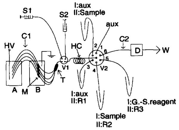
Schematic diagram of capillary format SIA system. HV High-voltage power supply; A, B pumping electrolyte solution containers; M membrane joint; C1 pumping capillary; T 4 × 1 union; HC holding coil; V1 four-way valve; S1, S2 syringes; V2 6 × 1 selector valve; R1, R2, R3 reagents; aux, unused auxiliary solution port. Reprinted with permission from Liu and Dasgupta 1994