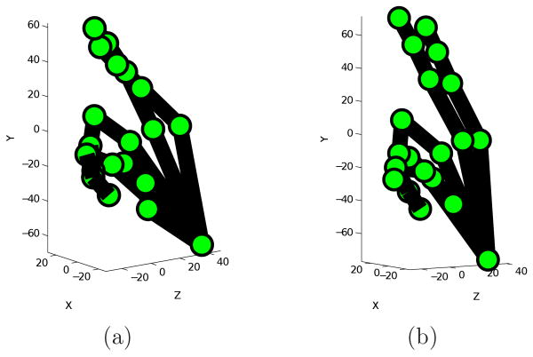
Abstract
The manual signs in sign languages are generated and interpreted using three basic building blocks: handshape, motion, and place of articulation. When combined, these three components (together with palm orientation) uniquely determine the meaning of the manual sign. This means that the use of pattern recognition techniques that only employ a subset of these components is inappropriate for interpreting the sign or to build automatic recognizers of the language. In this paper, we define an algorithm to model these three basic components form a single video sequence of two-dimensional pictures of a sign. Recognition of these three components are then combined to determine the class of the signs in the videos. Experiments are performed on a database of (isolated) American Sign Language (ASL) signs. The results demonstrate that, using semi-automatic detection, all three components can be reliably recovered from two-dimensional video sequences, allowing for an accurate representation and recognition of the signs.
Keywords: American Sign Language, handshape, motion reconstruction, multiple cue recognition, computer vision
1 Introduction
Sign languages are used all over the world as a primary means of communication by deaf people. American Sign Language (ASL) is one example, with broad uses in the United States. According to current estimates, in the United States alone, it is used regularly by more than 500, 000 people, and up to 2 million use it from time to time. There is thus a great need for systems that can interpret ASL (e.g., computer interfaces) or can serve as interpreters between ASL and English (e.g., in hospitals).
As other sign languages, ASL has a manual component and a non-manual one (i.e., the face). The manual sign is further divided into three components: i) handshape, ii) motion, and iii) place of articulation (6; 8; 10; 38; 31; 30)2. Most manual signs can only be distinguished when all three components have been identified. An example is illustrated in Fig. 1. In this figure, the words (more accurately called concepts3 or signs in ASL) “search” and “drink” share the same handshape, but have different motion and place of articulation; “family” and “class” share the same motion and place of articulation, but have a different handshape. Similarly, the concepts “onion” and “apple” could only be distinguished by their place of articulation – one near the eye region, the other at the chin.
Fig. 1.
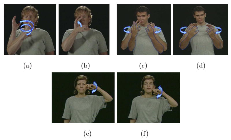
Example signs with identical handshape, different motion (a-b); same motion, different handshape (c-d); same motion, same handshape, different place of articulation (e-f). The meaning of these signs are: (a) search, (b) drink, (c) family, (d) class, (e) onion, and (f) apple.
If we are to build computers that can recognize ASL, it is imperative that we develop algorithms that can identify these three components of the manual sign. In this paper, we present innovative algorithms for obtaining the motion, handshape and place of articulation of the manual sign. This is obtained from a single video sequence of the sign. By place of articulation (POA), we mean that we can identify the location of the hand with respect to the face and torso of the signer. The motion is given by the path travelled by the dominant hand from start to end of the sign and by its rotation. The dominant hand is that which is used in single handed signs – usually the right hand for right-handed people. As we will see later, some signs actually involve the use of the two hands.
Finally, the handshape is given by the linguistically significant fingers (6). In each ASL sign, only a subset of fingers is actually of linguistic significance. While the position of the other fingers is irrelevant, the linguistically significant fingers are the ones associated to meaning. We address the issue as follows. First, we assume that while not all the fingers are visible in the video sequence of a sign, those that are linguistically significant are (even if only for a short period of time). This assumption is based on the observation that signers must provide the necessary information to observers to make a sign unambiguous. Therefore, the significant fingers ought to be visible at some point. With this assumption in place, we can use structure-from-motion algorithms to recover the 3D structure and motion of the hand. To accomplish this though, we need to define algorithms that are robust to occlusions. This is necessary because although the significant fingers may be visible for some interval of time, these may be occluded elsewhere. We thus need to extract as much information as possible from each segment of our sequence. Here, we also assume that algorithms will soon be developed for the detection or tracking of hand fiducials (e.g., knuckles). This is a very challenging task that has challenged researchers in computer vision for quite some time. To show the state of the art in this area, we develop a particle filter tracker. We will show that such a state-of-the-art approach is able to successfully track a large number of knuckles, but not all. To properly test the innovative algorithms presented in this paper, we will manually correct those fiducials that cannot be successfully tracked. Further research should indeed be directed to this problem.
Once the three components of the sign described above are recovered, we can construct a feature space to represent each sign. This will also allow us to do recognition in new video sequences. Here, we will also assume that each of the ASL signs has been properly segmented or appear in isolation. Combining signs into sentences would require the use of additional motion information and of the non-manuals.
There are computer vision systems which only use a single feature for sign representation and recognition (27; 4; 41; 26; 22; 43). In several of these algorithms, the discriminant information is generally searched within a feature space constructed with appearance-based features such as images of pre-segmented hands (4), hand binary masks (29; 1; 11; 43), and hand contours (34). The other most typically used feature is motion (41; 26). For recognition, one generally uses Hidden Markov Models (34; 29; 1), neural networks (41) or multiple discriminant analysis (4). These methods are limited to the identification of signs clearly separated by the single feature in use. Hence, even though these systems are useful for the recognition of a few signs, they are inappropriate as building blocks for the design of interfaces that can interpret and understand a large number of ASL signs. If we are to design a system capable of understanding ASL, we need to have a representation that uses the different components of the sign listed above. Also, these methods may be sensitive to (or biased toward) outliers or noise in the training data (44).
There are some existing linguistic-based algorithms for the recognition of signs. In general, these methods extract certain features by means of a data-glove (35; 16; 21; 36; 5; 32), some 2D image segmentation algorithm to delineate the hand (18; 2; 5), or a 2D hand contour extraction (33). Similar to the single feature-based sign recognition system defined above, Neuron Network (35; 32) or Hidden Markov Models (21; 36; 5) are used to classify each linguistic component. After all the components are classified, they are combined together for the classification of the signs using decision trees (16), dictionary lookups (33) or nearest neighbors (35).
There are problems in these existing methods. First, only the systems using data-glove (35; 16; 21; 36; 5; 32) are capable of capturing the 3D positions information. Unfortunately, the use of gloves limits the application of the algorithms greatly and they affect the psychological and physical execution of the sign. Thus, the performed signs are not in their natural conditions and most signers feel that these constraints greatly limits their communication channel. This is the main reason why several authors have moved to vision (33; 18). Unfortunately, in these algorithms, the features used to classify the components are simple 2D features. With these 2D features, the algorithms are very vulnerable to the inevitable self-occlusion of the hands, the variability of the signers and the point of view of the sign.
In comparison to these existing algorithms, our approach reconstructs the 3D handshape and the 3D motion of each sign in the signer's coordinate system from video sequences without the need of a data-glove. Therefore, our algorithm can be used to model and recognize a much larger amount of signs in a natural setting. In our approach, the 3D motion and place of articulation of the signs are also identified. With these three main linguistic components of ASL manual signs identified, our algorithm can provide robust recognition over a large variety of signers and points of view.
Our first goal is to define a robust algorithm that can recover the handshape and motion trajectory of each manual sign as well as their position with respect to the signer. In our approach, we allow not only for self-occlusions but also for imprecise localizations of the fiducial points. We restrict ourselves to the case where the handshape does not change from start to end, because this represents a sufficiently large number of the concepts in ASL (31) and allows us to use linear fitting algorithms. Derivations of our method are in Section 2.1. The motion path of the hand can then be obtained using solutions to the three point resection problem (14). Since these solutions are generally very sensitive to imprecisely localized feature points, we introduced a robustified version that searches for the most stable computation. Derivations for this method are in Section 2.2.
To recover the position of the hand with respect to the face, we make use of a recently proposed face detection algorithm (9). We find the distance from the face to the camera as the maximum distances travelled by the hand in all signs of that person. Using the perspective model, we obtain the 3D position of the face using the camera coordinate system. Then, the 3D position of the hand can be described using the face coordinate system, providing the necessary information to discriminate signs (10; 38; 6). Derivations are in Section 2.3. In Section 3, we detail on how each of these representations can be employed for the recognition of the sign. Experimental results are in Section 4, where we develop on the uses of the algorithms presented in this paper.
2 Modelling the Three Components of the Manual Sign
In this section, we derive algorithms for recovering the 3D information necessary to uniquely identify each sign.
2.1 Handshape reconstruction
First, we need to recover the 3D handshape of the signs in the video sequence. In our algorithm, handshapes are defined by the 3D-world positions of a set of hand points (fiducials), corresponding to the hand knuckles, finger tips and the wrist. Examples of the handshapes are shown in Fig. 2.
Fig. 2.
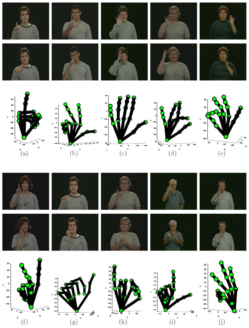
(a) Shown here are two example images with handshape “1” and the 3D reconstruction of the shape obtained with the proposed algorithm. Note that the two images correspond to two different signs sharing the same handshape. In (b-j) we show additional example images and corresponding 3D reconstruction for the following handshapes: “3,” “5,” “8,” “F,” “K,” “A,” “I,” “L” and “W.”
We denote the set of all 3D-world hand points as Pe = [p1, …, pn], where pi = [xi, yi, zi]T specifies the three dimensional coordinates of the ith feature point in the Euclidean coordinate system. The image points in camera j are given by Qj = AjPe+bj, j = 1, 2, …, m, where Qj = [qj1, …, qjn] is a matrix whose columns describe the image points, and Aj and bj are the parameters of the jth affine camera.
Our goal here in handshape reconstruction is to recover Pe, with regard to the object (i.e., hand) coordinate system, from known Qj, j = 1, 2, …, m.
The general approach to solve this kind of problems is to employ structure-from-motion algorithms. However, in our application we need to use the model defined above to recover the 3D shape even when not all the feature points are visible in all frames, i.e., with occlusions. Hence, the general approach cannot be employed in our case. To resolve this problem we work as follows.
First, we represent the set of affine equations defined above in a compact form as D = AP, where
| (1) |
When there is neither noise nor missing data, D is of rank 4 or less, since it is the product of A, a four column matrix, and P, which has 4 rows. If we consider a column vector of D as a point in the ℝ2m space, all the points from D lie in a 4-dimensional subspace of ℝ2m. This subspace, which is actually the column space of D, is denoted as  . If there was no missing data or noise, any four linear independent columns of D would span
  . Note that, in this case, factorization algorithms (15) can be applied directly to obtain
  .
.
When there is missing data in a column vector Di, any solution is possible. Hence, unless we have some additional information, we need to find a mechanism to recover it. To resolve this problem, we realize that the possible points in this column vector create an affine subspace, denoted  i.
i.
Let the four columns selection be Dh, Di, Dj, Dl, with h, i, j, l taking values in {1, 2, …, n}, and we enforce Dh ≠ Di ≠ Dj ≠ Dl. These four columns define the matrix
where nf is the number of possible Fk, and we note that the maximum value of nf is .
The four column vectors in Fk define four affine spaces  h,
h,  i,
i,  j, and
  l. Let us then denote the space spanned by the points from these four affine spaces
  h,
h,  i,
i,  j and
j and  l as
l as
Since there are no identical columns in Fk, we know that
In the noise free case, the spaces defined by  k intersect, which means that
  should be a subset of the intersection of all these spaces,
Unfortunately, with localization errors (i.e., noise in the data matrix) as well as errors caused by inaccurate affine modelling,  does not generally lie in every
  k. This implies that, generally, the intersection of all Sk is empty or of lower dimension than that needed to recover the structure of the hand.
To resolve this problem, one can use the null-space technique of (19). In this approach, the orthogonal space of  k is denoted as
. Let the matrix defining
be Nk. This allows us to write
which is the matrix representation of  ⊥.
⊥.
The null space of N is  . Thus, computing the Singular Value Decomposition (SVD) of N = UWVT and taking the four singular vectors (u1, u2, u3, u4) in U associated to the four smallest singular values, we obtain the spanning space
  . In fact, this is the closest solution as given by the Frobenius norm.
Once  has been properly estimated, we can use the non-missing elements of each column in D to fill in the missing positions of the data matrix. This is readily achieved as a linear combination of u1, u2, u3 and u4.
Note that in the approach described thus far, we use all possible Fk to construct N. This approach works best when there is no noise in the original data matrix. In general though, the data matrix has an unknown additive noise term. Ideally, we would like to use only those subsets that are less affected by this additive noise term. The problem is that in the absence of prior knowledge (which is our case), there is no mechanism to know which submatrices carry more noise than others. A solution to this problem is to select the submatrices based on their sensitivity to noise. A recent result (20) shows that the submatrices with most distinct column vectors are precisely those less affected by the additive noise term. In (20), a Deviation Parameter (DP) criterion is defined to measure the effects of noise in each submatrix. This DP value gives a measure of the sensitivity of a matrix to perturbation due to additive Gaussian noise. A large DP value for Fk means this submatrix is more vulnerable to noise. Missing elements also increase the DP value. Using this criterion, all Fk can be sorted in ascending order of relevance.
The next question we need to address is how many submatrices Fk are necessary to recover the 3D shape of the hand. Note that the DP criterion sorts the submatrices according to how noise affects them, but we still require to select the first r of these. To achieve this, we compute the error between the fitted matrix (i.e., our result) and the data matrix. In this process, only the visible elements of the matrix are compared by means of the Frobenius norm. Each possible value of r yields an error Er. The D̂ providing the minimum of these differences is selected as the solution. With D̂ computed, it is easy to decompose it into the (affine) shape P̂ and motion  using factorization.
As noted above, P̂ represents the affine shape of the hand. We also know that two affine shapes are equivalent if there exists an affine transformation between them. To break this ambiguity, we need to include the Euclidean constraints in our equations. Assuming the orthographic model of a camera, we can resolve the above problem by finding that which makes [Âj b̂j] H equal to the Euclidean model (with obvious notation). Orthographic cameras will be equivalent to the Euclidean space when the following constraints hold,
| (2) |
where
and
are the first and second rows of Âj, and
. Eq. (2) is a linear system for the symmetric matrix  . We can then recover
  as follows. First we initialize
  using the Cholesky decomposition as
. Second, we use the Levenberg-Marquardt algorithm for nonlinear fitting to find the best local solution (7).
The Euclidean shape of our object is then given by P̃ = H−1P. Fig. 2 shows example results for the recovery of the 3D handshapes “1,” “3,” “5,” “8,” “F,” “K,” “A,” “I,” “L” and “W.” Note that these signs correspond to the handshapes only, and do not have any meaning by themselves – unless they are combined with a motion and place of articulation.
If a column in D has a large number of missing elements, we may very well be unable to recover any 3D information from it. Note, however, that this can only happen when one of the fingers is occluded during the entire sequence, in which case, we will assume that this finger is not linguistically significant. This means we do not need to recover its 3D shape, because this will be irrelevant for the analysis and understanding of the sign. As argued above, this is a grounded hypothesis, because if a linguistically significant finger is not visible, the sign will either be ambiguous or meaningless.
2.2 Motion Reconstruction
We can now recover the 3D motion path of the hand by finding the pose difference between each pair of consecutive frames. That means, we need to estimate the translation and rotation made by the object from frame to frame using the camera coordinate system. A typical solution to this problem is given by the PNP resection problem (14). Also, in this case, the appropriate model to use is perspective projection, because we are interested in small changes.
In the three point perspective pose estimation problem, we employ three object points, p1, p2, and p3, with coordinates pi = [xi, yi, zi]T. Our goal is to recover these values for each of the points. Since the 3D shape of the object has already been recovered, the interpoint distances, i.e., namely a = ‖p2 − p1‖, b = ‖p1 − p3‖, and c = ‖p3 − p2‖, can be easily calculated.
As it is well-known, the perspective model is given by
| (3) |
where qi = (ui, vi)T is the ith image point and f is the focal length of the camera. The object is in the direction specified by the following unit vector
Now, the task reduces to finding those scalers, s1, s2 and s3, such that pi = siwi. The angles between these unit vectors can be calculated as
| (4) |
Grunert's solution to this problem (13), is based on the assumption that s2 = μs1 and s3 = νs1, which allows us to reduce the three point resection problem to a fourth order polynomial of ν:
| (5) |
where the coefficients A4, A3, A2, A1 and A0 are functions of interpoint distances a, b, c and the angles α, β, γ between all wi (14).
Such polynomials are known to have zero, two or four real roots. With each real root from (5), we can calculate μ, s1, s2, s3 and the values of p1, p2 and p3. Then, to recover the translation and rotation of the hand points, we use the nine equations given by
| (6) |
where wpi is a hand point as given by the world coordinate system, and R and t = [tx, ty, tz]T are the rotation matrix and translation vector we need to recover.
The nine entries of the rotation matrix are not independent. To reduce the 12 parameters to nine, we use a two-step method. 1) First, we note that the three points being used in the resection algorithm define a plane. We can now move and rotate this plane to match that of the x-y plane of the camera coordinate system. This rotation, R1, is given by the norm of the vectors defining the plane. Combined with the translation, t1, needed to position the plane at the origin of the coordinate system, we have
Here, we also have , i = 1, 2, 3. 2) In our second step, we use linear methods to solve the system of equations. Substituting wpi for p′i in (6), yields
Now denote the three columns of R2 r1, r2 and r3, and recall that r3 = r1 × r2. Furthermore, since , the three entries in r3 can be eliminated. This then becomes an easy to solve linear system of 9 unknowns and 9 equations, followed by a simple cross product to obtain the final solution.
The result of the two-step procedure described above results in the following transformation
With analogy to (6), we have
To make things easier to work with, we parameterize the rotation matrix using the three rotation angles rx, ry, and rz, as
| (7) |
Using this parametrization, the object is first rotated about the z-axis (in a clockwise direction when looking towards the origin) for angle rz, then about the y-axis (ry) and finally about the x-axis (rx). We also note that for each R recovered, depending on the free choice of the sign of cos ry, we have two sets of parameters: (rx, ry, rz) and (rx + π, π − ry, rz + π). Since these two solutions correspond to the same rotation, we only need to consider one of them. In the following, and without loss of generality, we will assume that the positive solution is the correct one.
The procedure described above provides a solution up to a sign ambiguity in the z direction. Note that aligning the plane defined by our triple with the x-y-plane implies z = 0. Hence there are two solutions for R. One is given by a negative z direction, i.e., the Normal of the plane pointing toward the negative quadrant. The other solution points toward the positive quadrant. This ambiguity will need to be considered in our derivations below.
Recall that the handshapes we work with are constant from beginning to end of each sign. This means that the rotations and translations obtained using the method described above for each of the possible triplets have to be the same. However, the polynomial defined in (5) may have more than one root and, in general, it is not known which of these roots correspond to the solution of our problem. To resolve this problem, we calculate all the solutions given by all possible triplets, and use a voting method to find the best solution.
In this approach, each solution for R is represented in a three-dimensional space defined by rx, ry and rz, i.e., each solution is a point (vector) in this 3D space. Once we have calculated the solutions of each triplet, we need to determine which of them is the best solution. To this end, we use a Parzen window approach, where a circular window of radius T is centered at the location of each vector. Then, the number of solutions (votes) in each of these Parzen windows is calculated. The final solution is defined as the mean of all the sample vectors within the window with most votes.
More formally, let us define the rotation obtained with the kth triplet as rk, and the window of radius T centered at rk as Nk. The number V (rk) of sample solutions found within each Nk is
and ns is the total number of triplets. Then, the most voted solution is given by
The same algorithms can be used to obtain a solution for t, yielding t̂. Note that in almost all voting methods, the determination of the best window width (2T in our algorithm) is very difficult even when we can assume that we know the distribution of the variable to be voted. In our algorithm, we use T = 10. This value is determined because that 2T (= 20) is about of the total ranges of the variables.
The results above allow us to obtain the final estimates of the rotation and translation. These are given by the means of all the samples in V (r̂) and V (t^). Note that in the process described above, the voting was used to eliminate the outliers from the solutions of Grunert's polynomials and the mean to provide an estimate based on the remaining inliers. This procedure is generally more robust than Grunert's solution.
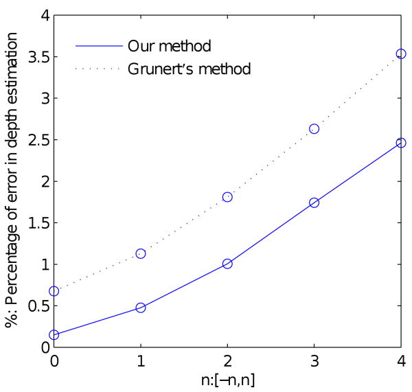
To show that our method can cope better with localization errors than the classical algorithm proposed by Grunert, we now provide some statistical analysis. For this purpose, we constructed synthetic handshapes with known motion parameters. Noise evenly distributed over [−n, n] (in pixels), with n = 1, 2, 3, 4, is added to the image points locations in both the horizontal and vertical axes. Error rates of our method and of the mean to the solutions of Gurnerts's algorithm are given in Fig. 3.
Fig. 3.
Shown here are the error curves corresponding to the solution given by Grunert's algorithm and the approach presented in this section.
2.3 Place of articulation
To successfully represent the 3D handshape and motion recovered using the above presented algorithms, we need to be able to describe these with respect to the signer not the camera. For this, we can set the face as a frame of reference. This is appropriate because the face provides a large amount of information and serves as the main center of attention (25). For example, the sign “father” is articulated using handshape “5” (as shown in Fig. 2 (c)), and with a forward-backward motion at the forehead (i.e., the thumb tapping the forehead). This is an easy sign to recognize, because there is a single meaning associated to it. However, the same sign signed at the chin means “mother.” Therefore, the same handshape and motion can have differen meanings when this is signed at different locations. Perhaps most interestingly, there are signs that modify their interpretation (or utility) with regard to where they are signed. For example, the concept “hurt” has distinct meanings depending on the place of articulation. When signed around the forehead, it means “headache,” but if signed around the stomach area it means “stomachache.” This means that to correctly interpret every concept (sign) in ASL, one needs to model its place of articulation too.
A convenient reference point to use is the face, because this can be readily and reliably detected using computer vision algorithms. In particular, we will use the center of the face as the origin of the 3D space, and describe the place of articulation with regard to this origin. Without loss of generality, we can further assume the face defines the x-y plane of our 3D representation and, hence, the location of the face also provides the direction of the x, y and z axes of our 3D coordinate system.
To properly define the face coordinate system just described, we employed a recently proposed face detection algorithm (9). In sign language, the hand often touches or comes across the face, which causes imprecise detection or miss-detections of the face. Given that the motion of the head is generally small during a sign, a Gaussian models can be utilized to fit the results. Let ft = [x, y, r]T, where [x, y] is the detected face center, r the radius, and t the frame number. We now fit a Gaussian model over the face detection in all frames, N(μf, Σf), with μf = (μx, μy, μr)T the mean and Σf = diag[σx, σy, σr] the variances. If several faces are detected in each image, they can be described as fti = [xti, yti, rti]T. The Mahalanobis distance
provides a simple measure of detection accuracy. Outliers can then be detected as those having distances larger than 1. The rest of the detections are considered inliers. From the inlier detections fti, the final detection ft in frame t is chosen as the one with smallest dti value. If there is no inlier detection in a frame, the location of the missed face is estimated using a linear interpolation of the neighboring frames. This robust face detection in video enables us to use a face model to partition the face into linguistically useful facial regions. This face model, which includes estimated locations of the principal internal facial features has been learned from sample face. Examples of this face detection procedure are shown in Fig. 4.
Fig. 4.

Face detection examples.
In our data-set, extracted from (23), the signing person stands in a fixed position. For each signer, we can define the distance from the signer to the camera as the maximum distance between the hand and the camera in all video sequences. However, simply taking the maximum distance as above makes it sensitive to outliers due to a single or a couple of inaccurately recovered motions. To resolve this issue, we employ the distance from the face of a signer to the camera, Zf, using a “modified maximum” defined as follows. We denote the maximum distance between the hand and the camera in the ith video sequences as , i = 1, …, m. Since the changes in are relatively small when compared to the distance between the face and the camera, we assume that Df can be modelled using a Gaussian model . If there is any , j = 1, …, m, satisfying , is considered an outlier and eliminated. The maximum of the remaining is taken as the value of Zf.
Once the face center [uf, vf]T, the radius rf and the distance from the face to the camera Zf have been computed, we calculate the position of the center of the face [Xf, Yf, Zf] in the camera coordinate system from and . We then define the x-y plane to be that provided by the face. Here, we assume that the face is planar, because we are only concerned with the main plane defined by the frontal view of the face. Whenever the face is frontal, there will only be a translation between the camera coordinate system and that of the face, i.e., Pf = Pc − [Xf, Yf, Zf]T. This is the most common case in our examples, since the subjects in (23) were asked to signed while looking at the camera. Using this approach, we can define the place of articulation with respect to the subjects' coordinate system.
Using the approach derived in Sections 2.1-2.2, we recover the 3D handshape and the 3D motion parameters. These are now described with respect to the place of articulation obtained from the method described in this section to uniquely represent the sign. Two examples of this complete modelling are in Fig. 5.
Fig. 5.
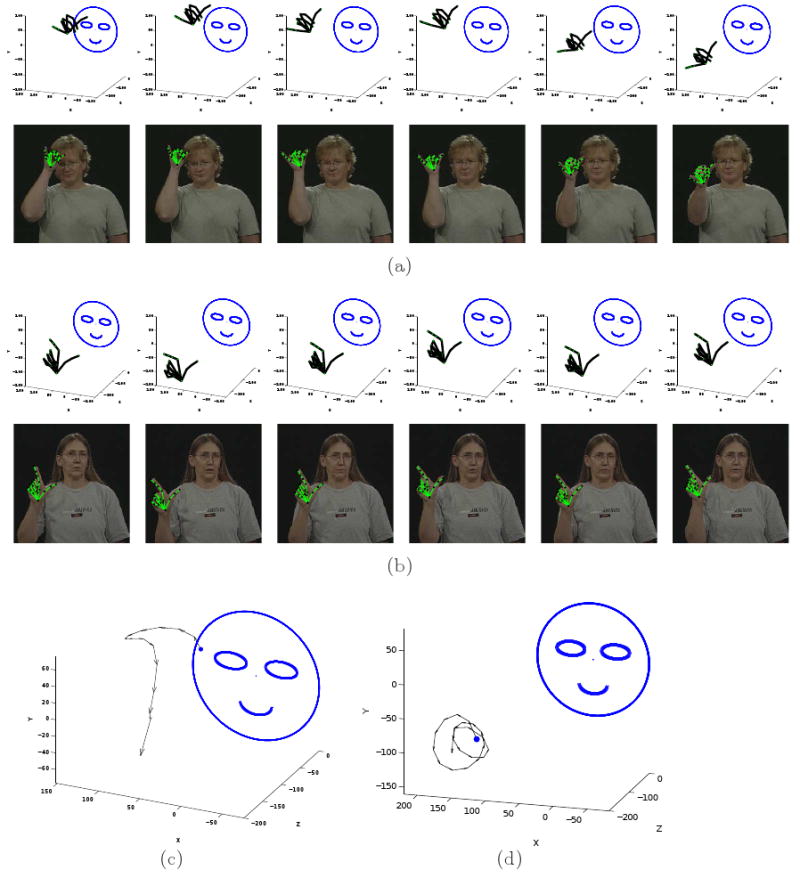
Shown here are the results of modelling the ASL concepts “forever” and “library.” In each sign, six example frames are shown. The 3D handshapes recovered by the proposed algorithm are shown in their 3D position and orientation with regard to the face coordinate system. This defines the place of articulation of the sign. The images with the corresponding reprojection of the reconstructed handshape using the 3D motion parameters recovered on top of the images are shown below each 3D display. In (a) we show the results corresponding to the ASL concept “forever.” In (b) we have the results for “library.” (c-d) The 3D trajectory recovered for the concept “forever” and “library,” respectively. The direction of motions is marked along the trajectories.
3 Recognition of ASL Signs
Thus far, we have presented an approach to describe an ASL manual sign using its three basic building blocks – handshape, motion and place of articulation. We will now introduce algorithms that use this representation to do recognition of ASL signs. We will also illustrate how the proposed approach can distinguish between very similar signs, i.e., signs that only diverge in one of these three components.
3.1 Handshape Recognition
The handshape model defined in Section 2.1 provides information of the spatial location of each of the hand knuckles, the tip of each finger and the wrist. Since each pair of consecutive points defines an underlying bone, our representation also includes information of the angle between these segments.
This spatial representation of the handshapes provides a simple mechanism for comparison. For this, the feature points need to be normalized by position and scale. Shift invariance is given by centering the mean of the hand points at the origin. The handshape is then scaled to have unit spectral norm. After normalization, least-squares (LS) is used to find the affine transformation between each pair of handshapes. Let P1 and P2 be a pair of handshapes after normalization, solving for and provides the least-squares solutions, where Pi ∈ ℝ3×20 are the twenty feature points describing the handshape, 4 as shown in Fig. 6, and Tj ∈ ℝ3×3 is an affine transformation. We take the mean of the two residuals as the error of our fitting process,
Fig. 6.
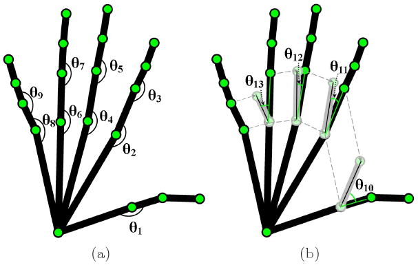
An illustration of (a) the joint angles used in our approach, and (b) the angle differences between fingers.
where is the 2-norm of a matrix.
The equation defined in the preceding paragraph is solely concerned with the spatial location of the feature points. Nonetheless, a handshape is also defined by the angles between different segments. Hence, it is necessary to incorporate this information in our formulation. Fig. 6 shows the different angles that we will use to compare two handshapes. In (a) we label the nine joint angles employed by our algorithm, and in (b) the angle difference between neighboring fingers. We describe these 13 angles of Pi in a vector as Θi = π−1(θ1, …, θ13)T. The comparison of the angle is
where is the 2-norm of a vector.
The two measures described above, Eshape and Eangle, provide a comparison of the handshapes using the spatial data and the angle differences. However, while some of these features are visible for a large number of frames in each video sequence, others are only visible in a very small interval. Since the algorithm introduced in Section 2 generally gains precision as more sample images become available, it is costumary to weight each of the features according to the number of times they are visible in the video sequence. This point is related to the “linguistically significant” fingers described earlier. In general the linguistically significant fingers will be visible for most of the duration of the video sequence, because these are the ones that carry the meaning. Again, this suggests a penalty term on the less relevant information. The visibility Vij of the jth point in handshape Pi is defined as
where pij is the jth point in handshape Pi. Note that the number of frames where pij is visible can be readily calculated during the (manual or automatic) detection process.
This new measurement allows us to write the vector of visibility vi = (Vi1, …, Vi20)T. The visibility difference between two handshapes is given by
Note that the range of values taken by each of the error measurements defined above is [0, 1]. This suggest a simple combination of the three errors as
| (8) |
Finally, for recognition purposes, a new test handshape P is classified as having the same meaning (class) as that Pi with smallest value for (8). More formally, let Pck be the kth sample of handshape c. Then, the handshape label h of P is given by
3.2 Motion Recognition
Motion is not only one of the basic elements of a sign without which recognition is not possible, it also carries additional information such as stress and other prosodic cues (40). The motion representation described in Section 2.2 is appropriate for these tasks. In this section, we show how it can also be used to do recognition of a set of basic ASL motions.
Most ASL signs include one or more of the following nine motion patterns: “up,” “down,” “left,” “right,” “forward,” “backward,” “circle,” “tapping”/“shake,” and “rotation.” To this list, we should include a tenth class which we will refer to as “none.” This final class specifies a sign with no associated motion (stationary).
To accurately detect each of these motions using the representation presented in Section 2.2, we need to determine the beginning and end of the sign. These are generally given by two known cues – the zero-crossings of the velocity curve and eye blinks. In some instances these could be difficult to determine. Additional features have to be considered when signs are signed in varying contexts (42) and research on discovering these features is an important area in linguistics.
To do recognition, we employ the translation vectors and the rotation matrices describing the motion from frame to frame. Before these are combined to describe the motion trajectory (path) of the sign, we need to eliminate the noise term. To do this we fit polynomial functions to the sequence of translation vectors we recovered. The degree of the polynomial is defined proportional to the number of frames used to estimate the motion trajectory.
For a sign of m frames, the recovered translation (after polynomial fitting) and rotation angles in the ith frame in the sequence are denoted and , respectively. The rotation matrix Ri describes the rotation between the hand and camera coordinate systems, which is given by (7). The rotation between frame i and i + 1 is then given by . The rotation between any two frames can now be parameterized using the three angles , and , as we did in (7). The translation between frames i and i + 1 is readily given by .
The process described above provides the translation and rotation information needed to define the path traveled by the hand. To properly define this, let
be the vector defining the translation and rotation made by the hand from frame i to frame i + 1.
Since we are not studying the prosody of the sign, we can eliminate the scaling factor in gj. This is in fact necessary to do classification of the motion regardless of other factors such as stress and intonation (40; 39). An exception is done to disambiguate the small movements of “tapping” and “shake” from the larger ones of “forward-backward” and “right-left.” An example, is the concept “father,” which uses tapping, and “interview,” which generally involves one or more forward-backward motions.
The translation between consecutive frames is used for recognizing the direction of movement. To be considered a valid detection, the translation ought to be larger than a minimum value Tν. On the strength aspect, a valid directed motion needs to be larger than the percentage Tνs of the total strength. If the signer is left-handed, the 3D motion will be mirrored in the x-axis. Note that in our system, we decompose diagonal motion into the motions in the x-axis, y-axis or z-axis. For example, for the diagonal motion “left and down”, both “left” motion and “down” motion are detected. In other words, we do not distinguish “left and down” from “left then down.”
Rotation is detected in the same manner. To be considered a real rotation, its velocity, given by the sum of the rotation angles , needs to be larger than a pre-specified threshold TR. Again, the strength of the total rotation angles should be larger than TRs to be considered a valid rotation.
Circular motions are trickier to detect and require of additional attention. To properly detect these, a nested mechanism is constructed. First we obtain a 3D trajectory , j = 1, …, ng, which is the result of a dense sampling from the polynomial fitted to the original trajectory , i = 1, …, m. Note that the larger the number ng is, the denser the sampling, which leads to a higher frame rate. Here, we use ng = 3m, since this corresponds to a frame rate of 90 frames per second, which is generally a good choice for circle motion detection. Since circles are signed as approximated 2D curves, we project the 3D trajectory onto several 2D planes. In the first step of the process, we consider four 2D projections, given by the x-y plane, the x-z plane, the y-z plane, and the plane defined by the first two principle components of the 3D points defining the curve. These four options consider a variety of commonly signed circular motions in ASL. Most use the first three choices – a rotation parallel to one of the planes defined by the signer's coordinate system. However, in some cases, and especially when the signer and observer (camera) are not in front of one another, the rotation needs to be defined according to the principal components of the motion. This option is slightly more sensitive to noise, but, because of the reasons cited here, it needs to be considered.
For each of the four 2D planes defined in the preceding paragraph, we have the projected 2D curve defined by the points , j = 1, …, ng. The ranges of the two directions are calculated and we denote the smaller one as D1 and the other as D2. In this 2D space, the points on the curves are densely sampled followed by the computation of the Hough transform for circles with radius rc. The range of the possible radius rc value to be tested is taken from D1/4 to D2/2. This is because the circles with radius smaller than D1/4 are too small to be valid circluar motions, and it is impossible to have a circle with its radius larger than D2/2 in this 2D curve space. The circle parameter (xc, yc) is voted for each rc. If the maximum vote is less than Tc, no circle is detected for this radius. Since the Hough transform will also give high votes for arcs, we need to check if the circle is complete. The angles Θi are calculated as the angles of the line connecting the points on the curve with the voted circle center (xc, yc). A continuous description Θ is obtained by filling in the gaps between consecutive points.
The regions of Θ can now be used to study the behavior of the hand. If in a region of Θ, there is a continuous interval [j1, j2] with changes of the sort 2π ∼ 2.2π, a circular motion may be present. To properly detect this, we move to the second step of our process. Here, the 3D points , j = j1, …, j2, are put through a Hough transforms analysis using the 2D points on the plane defined by the first two principle components of the 3D points with radius [rc − 3 ∼ rc + 3]. Note that only the 2D projected values are used, because, for the points in this interval to form a circle, they should lie on a plane. Similar to the above, the monotonicity of the angle is computed. Since the distances of the points to the circle center should be identical for circles, we require the distances in this interval to be closer to the radius and to have variances less than Tr. Here, Tr is set to (0.2rc)2, which is almost equivalent to allowing a 30% difference of the distances with respect to the radius. When an interval [j1, j2] satisfies these conditions, a circle with radius rc is detected. Fig. 7 shows an example detection of a circle defined in the x-z plane.
Fig. 7.

Shown here is an example of the detection of a circular motion. (a) The motion trajectory of an ASL sign. (b) The 2D projection of the sign trajectory. Shown in red is the detected circular motion. (c) The Hough transform result.
Note that in the above defined circle detection procedure, the direction of motion is ignored. This information is still present in the spatial information of gi. Note also that if a circle in the original 3D trajectory is mostly in the x-y plane, the x-z plane or the y-z plane, it is usually detected both in this plane and the 2D plane of the principle components with very similar radices. Since we are only interested in the existence of the circle motion, this will be treated as a single circular motion.
When a sign trajectory corresponds to a small motion, as in tapping and shaking, the motion detector defined in the preceding paragraphs will not generally detect them. Instead, these will be considered small components of the noise term. If we are to detect these motions robustly, we need to define a second set of thresholds whose sole purpose is to detect small motion patterns. For this task, the thresholds defined above are reduced to half of their value. The same motion extraction algorithm is then used to determine the existence of small components in the motion pattern. If such a small motion is detected we classified it as “tapping” whenever this involves movements about two opposite directions, and as “shaking” whenever there is a rotation involved. All other cases are classified as “none.”
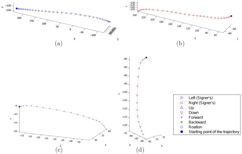
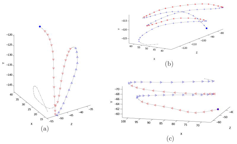
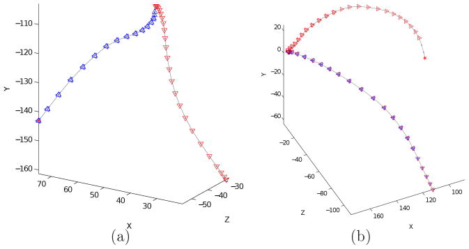
Figs. 8 and 9 show seven examples of motion detection obtained from actual ASL signs. Recall that many ASL concepts are signed using a sequence of two or more of the motion classes described in this section. The algorithm described above will detect the beginning and end of each of these. Two examples are given in Fig. 10. The first example corresponds to the motion of the sign “legal,” which includes a left followed by a down motion. The sign “forever” is signed with a right then forward motion.
Fig. 8.
Motion classification examples. The classes for each of the motions are : (a) left, (b) right, (c) forward, and (d) down.
Fig. 9.
Motion classification from signs including more than one class of movement. The results of the classification obtained with the propose algorithm are: (a) up– down, (b) forward-backward, (c) left-right.
Fig. 10.
Two example motions for the ASL signs (a) “legal,” and (b) “forever.”
Before we finish this section, it is worth mentioning that the motion recognition described in this section is invariant not only to the size of the sign, but also to the number of repetitions and length of the sign. This will prove very useful when recognizing signs from different subjects.
3.3 Detection of the place of articulation
In our modelling of ASL signs described in Section 2, the place of articulation is given with respect to the center of the face. To properly define the location of the hand, we use the hand fiducial that is closest to the face. The position of this fiducial with respect to the coordinate system of the face defines the POA (place of articulation) of the sign.
In some signs, the POA is not used to disambiguate signs but to define a specific location or meaning. For example, in the sign “you” or “she,” we point to the appropriate person. These signs generally happen away from the face. Thus, all the signs that are not close or around the face area will not be assigned any POA, and we label them with “none.”
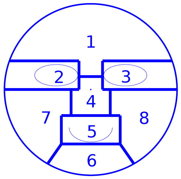
As mentioned earlier, the face is detected using a recently proposed algorithm (9), which also provides an estimate of the size (radius) of the face. The face area is divided into eight regions, Fig. 11. Each of these divisions is necessary to distinguish between several signs. For example, the forehead region (labeled “1” in Fig. 11) is used for paternal signs such as “father” and “boy,” while the chin region (labeled 6 in the figure) is related to maternal signs such as “mother” and “girl.”
Fig. 11.
Face template (model) used to specify the eight regions defining the place of articulation (POA) of a sign.
The template of the eight divisions shown in Fig. 11 is obtained from a set of manually marked images. Once the template is learned, it is used to estimate the location of these regions in every image in our ASL sequences.
When the POA is an “inherent feature,” that is, when the position does not change during the duration of the sign, the POA is that position. When the POA is a “prosodic feature,” that is, when it changes during the formation of the sign, we choose the position of the starting point or the ending position of the sign, whichever is closest to the face. The POA positions are then labeled with one of the eight classes shown in Fig. 11. The label is assigned according to the region that is closest to the POA. Fig. 12, shows a few examples of this process.
Fig. 12.
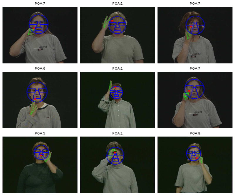
Example results of detecting the place of articulation in a variety of ASL signs. In each example image, we show the estimated face regions and the recovered handshape. The red dot indicates the POA found by the algorithm described in this section. The label of this POA is given by the face region closest to the red dot.
There are many signs that share a common handshapes but have different places of articulation. This is illustrated in Fig. 13. In the first example of this figure, the sign “car” is signed in front of the torso (far from the face), while the sign “lousy” occurs with the thumb touching the nose tip. In the second example, the sign“water” is signed with the tip of the index finger touching the chin, while “Wednesday” is signed on a side.
Fig. 13.
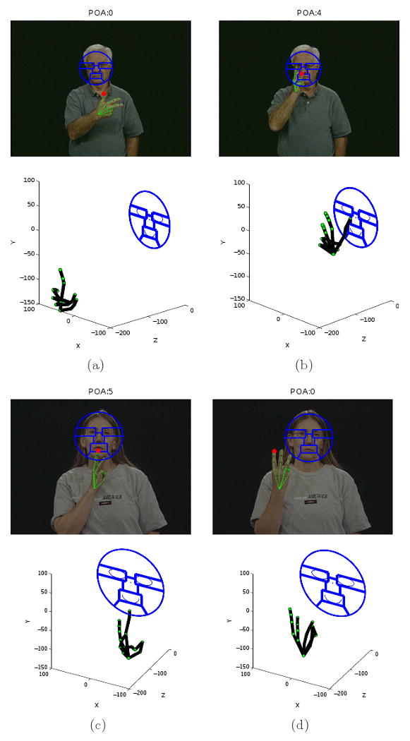
Two examples of ASL signs with common handshape but distinct place of articulation. (a) Car, (b) lousy, (c) water, and (d) Wednesday.
3.4 Using the three components for recognition
The first reason why one needs to model the three basic components of a sign (handshape, motion, and place of articulation) is because the three are needed to uniquely identify each possible sign.
A second important reason is because it allows for the recognition of previously unseen signs. Note that it only takes a sample of each handshape to be able to represent each possible sign that uses it. The other, unseen signs are given by the motion classes we have defined and every possible POA. For example, the sign “mother” is not present in the dataset of (23) that we will be using for testing. Nonetheless, the sign “father,” which is in the database, uses the same handshape and motion as “mother”. The only difference is that while father is signed on the forehead (area 1 in our model), mother is signed on the chin (area 6). If we are to recognize the concept “mother,” all we need to know is that it is the same as father but with a different POA; we do not actually need to provide a video sequence with the sign or train any classifier.
This is a key advantage of the proposed system. It means that our system can be trained with a small number of signs. Additional concepts (or word) can be added from a dictionary, e.g., (31).
To be able to do this type of recognition, we propose to combine the information we have from each signed concept in a tree-like structure. In this approach, all the training samples are used to obtained the 3D reconstruction of the hands. Each training sample is labeled with the meaning (concept label) and type of handshape. For example, if we have the sign “legal” as a sample video, which is signed with a “L” handshape, we will give it two labels: “legal” and “L,” specifying the meaning and type of handshape. This training sample is used to learn that “legal” is signed with handshape “L” and a left-down motion. We can now teach the system that the concept “library” is signed with a “L” handshape and a circular motion, without the need to provide any sample video – much like ASL is taught in the classroom. The system is now ready to recognize these two ASL signs.
Our tree structure works as follows. Handshapes are used at the first level of the tree structure. For each learned handshape, we add as many branches as needed to represent all the concepts that the system has in memory. As we have seen, many signs have identical handshape and motion but are signed in a different POA. If this is the case, we add a third level in our hierarchy to specify the different POAs needed to make the distinction.
Note that one could also design a tree structure that starts with POAs or motion categories at the first level and then employ the other two components in the second and third levels of the hierarchy. Here, we chose to use the handshapes in the first level because of the structure of the dataset we are going to use as in Section 4. In fact, the tree structure should always be fitted to the vocabulary of the signs in use. And it needs to be adjusted when new signs are added into the vocabulary as we will show later. On the other hand, the easy adjustment of this tree structure is the only thing that is required when new signs are added. No additional training is needed. Also note that if hand orientation is needed to distinguish signs in the vocabulary, one can add another level for this component in the tree structure conveniently.
As a final note, one could design a system which does not require of any training video sequence. The handshape could be provided by an interactive tool that allow the user to work with a hand model similar to that depicted in Fig. 6. The system could then be entirely trained with labels, without the need to collect any large database of signs. This would however require of expertise users to train the system. The advantage of using a training video to learn the 3D handshape, is that we do not need to provide any 3D model of it since the system will learn this by itself.
4 Experimental Results
To obtain our results we employ the video sequences of the Purdue ASL Database (23), which include challenging sets of ASL signs using a variety of handshapes, motions and POA. The database contains 2, 576 video sequences. The resolution of the videos is 640 × 480 pixels with the hand size varying from a minimum of (approximately) 55×55 to a maximum of (approximately) 140 × 140 pixels. The size of the face in the video sequences varies from 110 × 110 to 160 × 160 pixels.
The first set of the video sequences in the Purdue ASL set include a large number of basic handshapes. This corresponds to a set of video clips in which each person signs two ASL concepts with distinct meanings. Each sign is given by a common handshape but distinct motion and/or POA. Therefore, these video sequences provide an adequate testing ground for the proposed system. Since these ASL sequences do not include different palm hand orientation, we have not included this in our model. Nonetheless, this can be readily added, because the palm orientation is directly given by the 3D reconstruction and the reference coordinates as given by the face location.
In our experiments, we used the video sequences of 10 different subjects. Each subject performed 38 distinct signs. Since each handshape is shared by two different signs, there is a total of 19 different handshapes. The handshapes and the corresponding signs are shown in Table. 1.
Table 1.
In this table, the first column describes the type of handshape, while the second column specifies the two meanings the observed in the Purdue database.
| Handshapes | Signs | |
|---|---|---|
| 1 | You | Only-one |
| 3 | car | lousy |
| 5 | father | tree |
| 8 | jerk | sick |
| A | daily | girl |
| B | house | present |
| C | drink | search |
| E | East | elevator |
| F | fruit | cat |
| I | deaf school | interview |
| K | see | kitchen |
| L | legal | library |
| O | none | empty-head |
| R | rope | Ronnie |
| U | honor | hard-of-hearing |
| V | vinegar | dive |
| W | water | Wednesday |
| X | can | apple |
| Y | same | forever |
In general, it is very difficult to accurately track the knuckles of the hand fully automatically. This is mainly due to the limited image resolution, inevitable self-occlusions and the lack of salient characteristics present in the video sequences. Progress is being made toward automatic detections, but current existing algorithms require high quality images and slow motions of the hands (12; 37), which are not usually the case in ASL video sequences. Since our goal is to test the performance of the algorithms presented in this paper, not that of an automatic hand tracker, we use a semi-automatic hand point tracking algorithm to obtain the positions of the visible hand points in the image sequences of each sign.
This semi-automatic tracking algorithm works as follows. To begin with, the positions of the visible hand points (in the first frame of the sign) in each video sequence are manually marked. The rest of the hand points are labelled as occluded fiducials. Then, a tracker based on the idea of the Sampling Importance Resampling (SIR) particle filter (3) is employed to follow the 2D image movements of each of the hand fiducials. In our implementation, appearance and geometrical features of the hand points are used to estimate the weights of the particles. The appearance features used include the cropped images of the visible hand points, while the geometrical features employed the lengths of finger segments and the angles separating them. After the automatic tracking results are obtained, they are shown to the user. In this way, the user can correct any inaccuracies of the tracker and can mark those points that had just become visible. Similarly, newly occluded hand points can be labelled as such. After the tracking has been corrected or verified by the user, the particle filter provides the detection result for the next frame. This process is iterated until we have accounted for all the frames in the video sequence.
The above defined tracking algorithm is applied to the ASL video sequences used in our experiment. The trackings obtained with this algorithm are almost always correct, except when there are occlusions or large changes between consecutive frames. During our experiments, about 28% of the automatically tracked hand points had to be manually corrected. We can conclude that this tracking algorithm greatly reduces the work load that would be required by manual marking, but that additional research is needed in this area before we can successfully resolve the problem of fully automatic recognition of ASL signs.
For each of the 380 video sequences, the 3D handshape is reconstructed from the tracked hand point positions using the algorithm presented in Section 2.1. Having the 3D handshape, the motion parameters associated to each of the frames are recovered using the method described in Section 2.2. The POA is given by the algorithm defined in Section 3.3.
Our first experiment is intended to test the validity of the recovered 3D handshape. Note that the remaining system is based on this and, hence, a poor reconstruction could lead to later problems. For this experiment, we chose the sequences of 3 subjects as the training set, while using the rest of the sequences belonging to the remaining 7 subjects as the testing set. All possible 120 combinations of this 3-fold cross-validation test are employed. A handshape is correctly recognized if the class label obtained by the recognition algorithm is the same as the true label. The final recognition results are defined as the total number of correct recognitions over the total number of test sequences. The recognition rate is 100%.
This result shows that our algorithm provides robust reconstruction of the 3D handshapes, although the detection and tracking of the hand fiducials contains noise and large occlusions. Especially amongst the 19 handshapes in our experiments there are several similar handshapes. For example, the handshapes “U” and “R” are very similar. The only slight difference between them are the positioning of the index finger and the middle finger. In handshape “U,” the index finger and the middle finger go together – straight and parallel to each other. In handshape “R,” the two fingers are slightly crossed, as shown in Fig. 14. An excellent 3D reconstruction is needed to be able to disambiguate the two. Our system achieves this thanks to the multiple features encoded into the system – including spatial information and angles.
Fig. 14.
Shown here are examples of similar handshapes. Handshapes: (a) “R,” and “U.”
Now that we know that the handshape representation and recognition system used provide an adequate bases to distinguish between a large variety of signs, we would like to see how well these results combine with the motion features obtained by our system. In our second experiment, the signs with the same handshape and motion are considered identical. The goal of this experiment is to determine whether the system can disambiguate signs regardless of their POA. For example, the concept “father” and “tree” have the same handshape and motion patterns (as given by our representation, since shake and tap are classified in the same class). Nonetheless, these need to be distinguished from the other signs having a common handshape but a distinct motion. Using the same cross-validation procedure described above, we randomly chose the video sequences of 3 subjects for training, and use the rest for testing. The recognition rate is 95.5%.
The third experiment will test the accuracy of our system in classifying ASL signs from different subjects when using the three basic components of the manual sign. Hence, in this experiment, the goal is to determine the true underlying meaning of each sign. This means, we are now required to correctly discriminate the three basic components of the sign – its handshape, motion and POA. This is thus the most challenging of the experiments. Using the same 3-fold cross-validation test as above, the final recognition rate is 93.9%. In Fig. 15, we show an example of the outcome of the proposed system for the signs “car” and “lousy”. Their corresponding tree structure are shown in Fig.16.
Fig. 15.
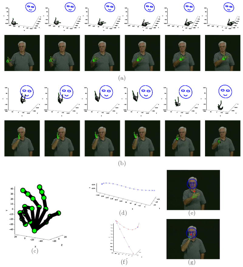
(a-b) The modelling results for the ASL signs “car” and “lousy.” In each sign, six example frames are shown. The 3D handshapes recovered by the proposed algorithm are shown in their 3D position and orientation with regard to the face coordinate system. The images with the corresponding reprojection of the reconstructed handshape using the 3D motion parameters recovered on top of the images are shown below each 3D display. (c) The handshape of the signs: “3.” (d-e) The motions of the signs. (f-g) The POAs of the signs.
Fig. 16.
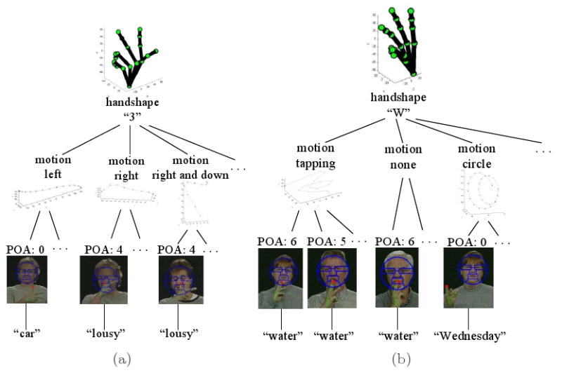
Shown here are examples of the tree structures generated by the proposed approach for the ASL signs: (a) “car” and “lousy,” and (b) “water” and “Wednesday.”
These results suggest that the tree structures recognition approach presented in this paper is appropriate to represent and recognize ASL signs even when these are signed by different people. Two examples of such tree structure are shown in Fig. 16. When we recognize the handshape in a sequence as “3,” we need to further subdivide the classifier into several sub-sections, as shown in Fig.16(a). If the motion category is “left” and the POA is region 1, the ASL concept is “car.” If the motion class is “right” or “right-down” and the POA is region 0 (“none”), the ASL concept is “lousy.” Similarly, when we recognize the handshape as “W,” we follow the tree sub-structures in Fig.16(b). In this case, if the motion category is “tapping” or “none” and the POA is region 5 or 6, the concept is “water.” But, if the motion is a “circle” and the POA is region 0, the recognized concept is “Wednesday.”
It is important to note that the efficiency of this tree structure does not diminish when the number of concepts (signs) increases. This is in contrast to other approaches, as in hidden Markov models, neural networks and discriminant analysis. This is an important property, which should allow us to move from small vocabularies to large ones in the near future.
We also note that since in the Purdue database there are only two concepts which are associated with handshape “3,” we can simplify the tree descriptors to that shown in Fig. 17(a), where we only use the motion to decide the concept. If the motion is “left,” the ASL concept is “car”, otherwise “lousy.” A similar simplification is possible for the “water” and “Wednesday” signs as illustrated in Fig. 17(b). These simplifications are important, because they make the system more robust to signing variations. Note that native signers may very well be using a similar simplification approach. This then leads to different ways to sign the same ASL concept – not because they are different signs, but because the feature that was left out from the representation is now free to vary without affecting the meaning of the sign. Additional simplifications could be extracted by means of discriminant analysis algorithms, for which stable algorithm can be defined (24). However, if a new sign is learned that needs to incorporate the feature we had eliminated, then such variations are no longer possible and the original representation has to be recovered.
Fig. 17.
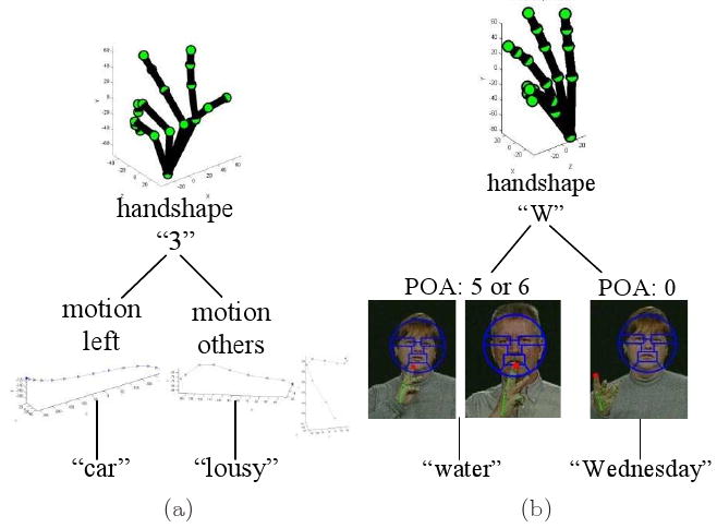
Shown here are examples of the simplified tree structures for the manual signs: (a) “car” and “lousy,” and (b) “water” and “Wednesday.”
Our last experiment is intended to test the algorithm's ability to recognize new (unseen, untrained) signs, which is one of the main advantages of the proposed approach. For this experiment, we use the same cross validation method and the same dataset of 10 subjects, 19 handshapes and 38 signs as in the previous experiments. However, in testing we include one more sign: “King,” for each of the subject. What we need to do is to add the configuration of the sign “King” (handshape “K,” motion “right” and “down,” and POA “0”) into the tree structure. Fig. 18 shows how the tree structure under handshape “K” is updated. Note that there is no need to change the rest of the tree structure.
Fig. 18.
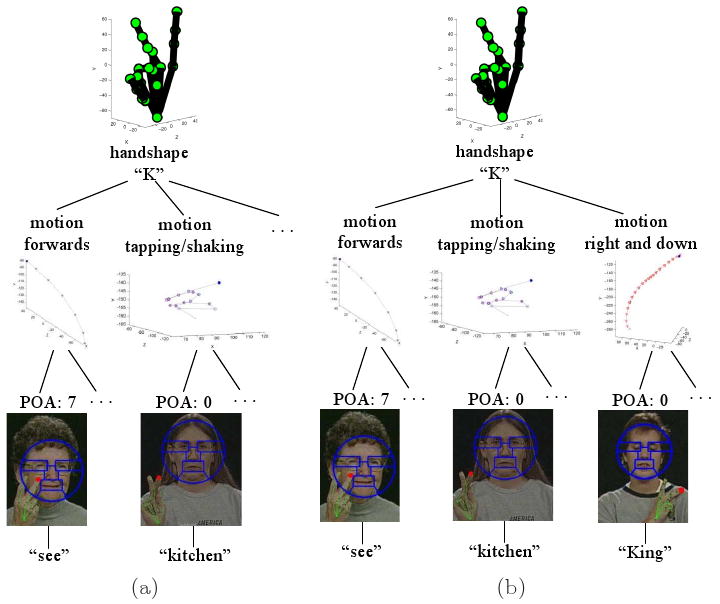
Shown here are examples of the tree structures for the manual signs with handshape “K”: (a) for the original vocabulary, and (b) for the new vocabulary when a new sign “King.”
The recognition rate of the new signs “King” is 89.5% and the recognition rate of the whole vocabulary including the new signs “King” is 93.5%. This shows how the proposed algorithm is able to recognize new ASL signs with a single adjustment of the tree structure.
5 Conclusions
To successfully represent ASL signs, one needs to be able to recover their 3D position, handshape and motion. In this paper we have presented a set of algorithms specifically designed to accomplish this. Since in ASL, self-occlusions and imprecise detections are common, we have presented extensions of the structure-from-motion and resection algorithms that appropriately resolve these issues. We have also introduced the use of a face detector to identify the place of articulation of the sign. These components together complete the representation of a sign and allow us to uniquely identify signs that only diverge in one of these three variables.
We have then developed specific algorithm for the recognition of new signs, and we have introduced a tree-based classifier that can be trained with video sequences or simple dictionary-like instructions. Experimental results using a database of hard to distinguish signs demonstrated the robustness of the proposed algorithms.
We have also noted that the learning system defined in this contribution – the tree structure – does not limit the number of concepts learned, as hidden Markov models or other approaches would. This should facilitate the extension of the proposed algorithm to do recognition in large vocabularies. From this, we will be able to move to recognition in context, i.e., sentences. However, new fundamental results will be needed to disambiguate signs from context, since the same sign can be articulated differently depending on the contents of its sentence.
Acknowledgments
We are grateful to Ronnie Wilbur for her wonderful descriptions of the inner-workings of ASL. This research was supported in part by grant R01-DC-005241 from the National Institutes of Health and grant IIS-07-13055 from the National Science Foundation.
This research was supported in part by a grant from the National Institutes of Health and a grant from the National Science Foundation.
Footnotes
A fourth component can be included to this list: palm orientation. In this paper we do not directly model this, because, as we will show, it can be obtained from the other three components.
It is important to note that in ASL signs correspond to concepts not words. In many instances, more than one signed concept is needed to represent a word. These are known as compound signs. This is the case, for example, when we want to sign the word “lawyer,” which requires the concepts “law” and “person.”
In this LS fitting process, we only employ the common visible data of both handshapes. In some cases this results in a smaller number of columns.
Publisher's Disclaimer: This is a PDF file of an unedited manuscript that has been accepted for publication. As a service to our customers we are providing this early version of the manuscript. The manuscript will undergo copyediting, typesetting, and review of the resulting proof before it is published in its final citable form. Please note that during the production process errors may be discovered which could affect the content, and all legal disclaimers that apply to the journal pertain.
Contributor Information
Liya Ding, Email: dingl@ece.osu.edu.
Aleix M. Martinez, Email: aleix@ece.osu.edu.
References
- 1.von Agris U, Schneider D, Zieren J, Kraiss K. Rapid Signer Adaptation for Isolated Sign Language Recognition. Proc IEEE Computer Vision and Pattern Recognition. 2006 Jun;:159–159. [Google Scholar]
- 2.Aran O, Ari I, Benoit A, Carrillo AH, Fanard FX, Campr P, Akarun L, Caplier A, Rombaut M, Sankur B. Sign Language Tutoring Tool. Report in ENTERFACE Workshop. 2006 [Google Scholar]
- 3.Arulampalam MS, Maskell S, Gordon N, Clapp T. A Tutorial on Particle Filters for Online Nonlinear/Non-Gaussian Bayesian Tracking. IEEE Transactions on Signal Processing; Proc. IEEE Computer Vision and Pattern Recognition, 2008; Feb, 2002. [Google Scholar]
- 4.Cui Y, Weng J. Appearance-Based Hand Sign Recognition from Intensity Image Sequences. Computer Vision Image Understanding. 2000;78(2):157–176. [Google Scholar]
- 5.Brashear H, Henderson V, Park KH, Hamilton H, Lee S, Starner T. American Sign Language Recognition in Game Development for Deaf Children. Proc Conf on ACM SIGACCESS on Computers and Accessibility; 2006. [Google Scholar]
- 6.Brentari D. A prosodic model of sign language phonology. MIT Press; 2000. [Google Scholar]
- 7.Dennis JE, Schnabel RB. Numerical Methods for Unconstrained Optimization and Nonlinear Equations (Classics in Applied Mathematics) Society for Industrial Mathematics. 1987 [Google Scholar]
- 8.Ding L, Martinez AM. Three-Dimensional Shape and Motion Reconstruction for the Analysis of American Sign Language. Proc the 2nd IEEE Workshop on Vision for Human Computer Interaction; 2006. [Google Scholar]
- 9.Ding L, Martinez AM. Precise Detailed Detection of Faces and Facial Features. Proc IEEE Computer Vision and Pattern Recognition. 2008 [Google Scholar]
- 10.Emmorey K, Reilly J, editors. Language, gesture, and space. Hillsdale, N.J.: Lawrence Erlbaum; 1999. [Google Scholar]
- 11.Fang G, Gao W. A SRN/HMM System for Signer-independent Continuous Sign Language Recognition. Proc IEEE Automatic Face and Gesture Recognition. 2002 [Google Scholar]
- 12.Gorce ML, Paragios N, Fleet DJ. Model-Based Hand Tracking with Texture, Shading and Self-occlusions. Proc IEEE Computer Vision and Pattern Recognition. 2008 [Google Scholar]
- 13.Grunert JA. Das Pothenotische Problem in erweiterter Gestalt nebst Über seine Anwendungen in der Geodäsie. Grunerts Archiv für Mathematik und Physik, Band 1. 1841:238–248. [Google Scholar]
- 14.Haralick RM, Lee C, Ottenberg K, Nolle M. Review and Analysis of Solutions of the Three Point Perspective Pose Estimation Problem. International Journal of Computer Vision. 1994;13(3):331–356. [Google Scholar]
- 15.Hartley R, Zisserman A. Multiple View Geometry in Computer Vision. Cambridge University Press; 2003. [Google Scholar]
- 16.Hernandez-Rebollar JL, Kyriakopoulos N, Lindeman RW. A New Instrumented Approach for Translating American Sign Language into Sound and Text. Proc IEEE Automatic Face and Gesture Recognition. 2004 [Google Scholar]
- 17.Holden EJ, Owens R. Visual Sign Language Recognition. Proc Int'l Workshop Theoretical Foundations of Computer Vision. 2000:270–287. [Google Scholar]
- 18.Imagawa K, Matsuo H, Taniguchi Ri, Arita D, Lu S, Igi S. Recognition of Local Features for Camera-Based Sign Language Recognition System. Proc IEEE Pattern Recognition. 2000;4:849–853. [Google Scholar]
- 19.Jacobs DW. Linear Fitting with Missing Data for Structure-from-Motion. Computer Vision and Image Understanding. 2001;82(1):57–81. [Google Scholar]
- 20.Jia H, Martinez AM. Low-Rank Matrix Fitting Based on Subspace Perturbation Analysis with Applications to Structure from Motion. IEEE Transon Pattern Analysis and Machine Intelligence. 2009 May;31(No. 2):841–854. doi: 10.1109/TPAMI.2008.122. [DOI] [PubMed] [Google Scholar]
- 21.Liang RH, Ouhyoung M. A Real-Time Continuous Gesture Recognition System for Sign Language. Proc IEEE Automatic Face and Gesture Recognition. 1998:558–565. [Google Scholar]
- 22.Lichtenauer J, Hendriks E, Reinders M. Sign Language Recognition by Combining Statistical DTW and Independent Classification. IEEE Trans Pattern Analysis and Machine Intelligence. 2008;30(11):2040–2046. doi: 10.1109/TPAMI.2008.123. [DOI] [PubMed] [Google Scholar]
- 23.Martinez AM, Wilbur RB, Shay R, Kak AC. The Purdue ASL Database for the Recognition of American Sign Language. Proc. IEEE Multimodal Interfaces; Pittsburgh (PA). Nov, 2002. [Google Scholar]
- 24.Martinez AM, Zhu M. Where Are Linear Feature Extraction Methods Applicable? IEEE Trans Pattern Analysis and Machine Intelligence. 2005;27(12):1934–1944. doi: 10.1109/TPAMI.2005.250. [DOI] [PubMed] [Google Scholar]
- 25.Messing MS, Campbell R. Gesture, speech, and sign. Oxford University Press; 1999. [Google Scholar]
- 26.Nayak S, Sarkar S, Loeding B. Distribution-based dimensionality reduction applied to articulated motion recognition. IEEE Trans Pattern Analysis and Machine Intelligence. 2009 May;31(No. 2):795–810. doi: 10.1109/TPAMI.2008.80. [DOI] [PubMed] [Google Scholar]
- 27.Ong SCW, Ranganath S. Automatic Sign Language Analysis: A Survey and the Future beyond Lexical Meaning. IEEE Trans on Pattern Analysis and Machine Intelligence. 2005;27(6) doi: 10.1109/TPAMI.2005.112. [DOI] [PubMed] [Google Scholar]
- 28.Sagawa H, Takeuchi M. A Method for Recognizing a Sequence of Sign Language Words Represented in a Japanese Sign Language Sentence. Proc IEEE Automatic Face and Gesture Recognition. 2000:434–439. [Google Scholar]
- 29.Starner T, Pentland A. Real-Time American Sign Language Recognition Using Desk and Wearable Computer Based Video. IEEE Trans Pattern Analysis and Machine Intelligence. 1998;20(12) [Google Scholar]
- 30.Stoke WC. Journal of Deaf Studies and Deaf Education. 1. Vol. 10. Oxford University Press; 2005. Sign Language Structure: An Outline of the Visual Communication Systems of the American Deaf. [DOI] [PubMed] [Google Scholar]
- 31.Stoke WC, Casterline DC, Croneberg CG. A Dictionary of American Sign Language on Linguistic Principales. Linstok Press; 1976. [Google Scholar]
- 32.Su MC. A Fuzzy Rule-Based Approach to Spatio-Temporal Hand Gesture Recognition. IEEE Trans on Systems, Man, and Cybernetics, Part C: Applications and Reviews. 2000 May;30(2):276–281. [Google Scholar]
- 33.Tamura S, Kawasaki S. Recognition of Sign Language Motion Images. Pattern Recognition. 1988;21(4):343–353. [Google Scholar]
- 34.Tanibata N, Shimada N, Shirai Y. Extraction of Hand Features for Recognition of Sign Language Words. Proc International Conf Vision Interface. 2002:391–398. [Google Scholar]
- 35.Vamplew P, Adams A. Recognition of Sign Language Gestures Using Neural Networks. Neuropsychological Trends. 2007 April;(1):31–41. [Google Scholar]
- 36.Vogler C. PhD thesis. Univ of Pennsylvania; 2003. American Sign Language Recognition: Reducing the Complexity of the Task with Phoneme-Based Modeling and Parallel Hidden Markov Models. [Google Scholar]
- 37.Wang J, Athitsos V, Sclaroff S, Betke M. Detecting Objects of Variable Shape Structure With Hidden State Shape Models. IEEE Transactions on Pattern Analysis and Machine Intelligence. 2008;30(3):477–492. doi: 10.1109/TPAMI.2007.1178. [DOI] [PubMed] [Google Scholar]
- 38.Wilbur RB. American Sign Language: Linguistic and applied dimensions. Second. Boston: Little, Brown; 1987. [Google Scholar]
- 39.Wilbur RB, Martinez AM. Physical Correlates of Prosodic Structure in American Sign Language. Chicago Linguistic Society. 2002;38 [Google Scholar]
- 40.Kuhn N, Ciciliani TA, Wilbur RB. Phonological parameters in Croatian Sign Language. IEEE Trans Pattern Analysis Machine Intelligence. 2006;9(No. 1-2):33–70. [Google Scholar]
- 41.Yang M, Ahuja N, Tabb M. Extraction of 2D Motion Trajectories and Its Application to Hand Gesture Recognition. IEEE Trans Pattern Analysis Machine Intelligence. 2002 Aug;24(8):1061–1074. [Google Scholar]
- 42.Yang R, Sarkar S, Loeding B. Enhanced Level Building Algorithm for the Movement Epenthesis Problem in Sign Language Recognition. Proc IEEE Conf on Computer Vision and Pattern Recognition; 2007. [Google Scholar]
- 43.Ye J, Yao H, Jiang F. Based on HMM and SVM Multilayer Architecture Classifier for Chinese Sign Language Recognition with Large Vocabulary. Proc IEEE International Conference on Image and Graphics; 2004. [Google Scholar]
- 44.Zhu M, Martinez AM. Pruning Noisy Bases in Discriminant Analysis. IEEE Transactions on Neural Networks. 2008;19(1):148–157. doi: 10.1109/TNN.2007.904040. [DOI] [PubMed] [Google Scholar]


