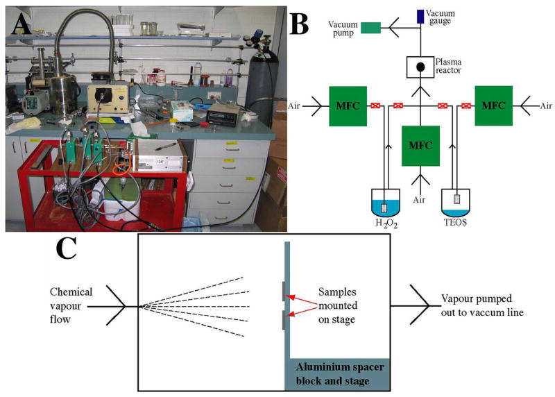
Fig. 1.
The PECVD experimental set-up that was used for coating PECVD-Si films on Ti substrates. A photograph of the set-up is shown in (A). An illustration of the vapour delivery system is shown in (B). MFC denotes mass flow controller. An illustration of Ti samples (for PECVD-Si coating) mounted on the stage in the glass chamber of the Harrick radio-frequency plasma generator is shown in (C).

